STM32 & CLion
Scott
This guide uses CLion 2019.1 with integrated embedded support, and will cover the entire process of creating a new STM32F4 project, setting up the UART, and then integrating Electric UI.
We also have a Github repo with a DMA based UART example for the STM32F4 which is a bit more advanced than this guide.
A STM32F407 Discovery development board is used, but most STM32 targets should also work fine.
Project Creation and Setup
We'll basically follow the normal project creation process with CLion's embedded support. This JetBrains article shows the process and covers dependancy resolution and configuration. We'll also cover project creation basics, but will configure the peripherals and change firmware needed to actually get things running.
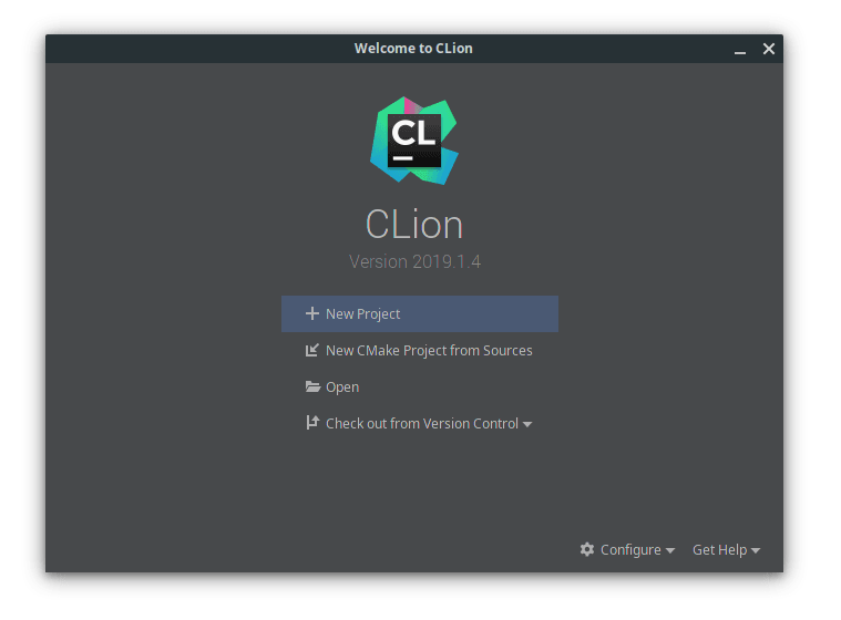
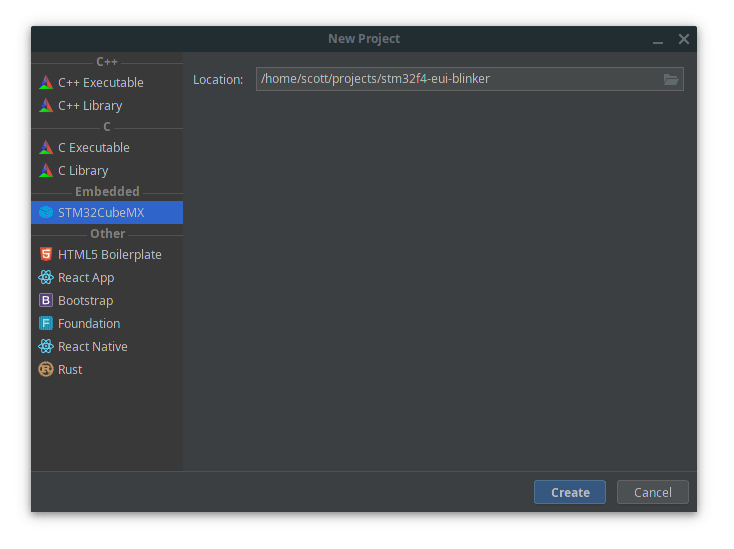
Create a new project with the STM32CubeMX template. The template will populate a .ioc file which you need to edit in CubeMX.
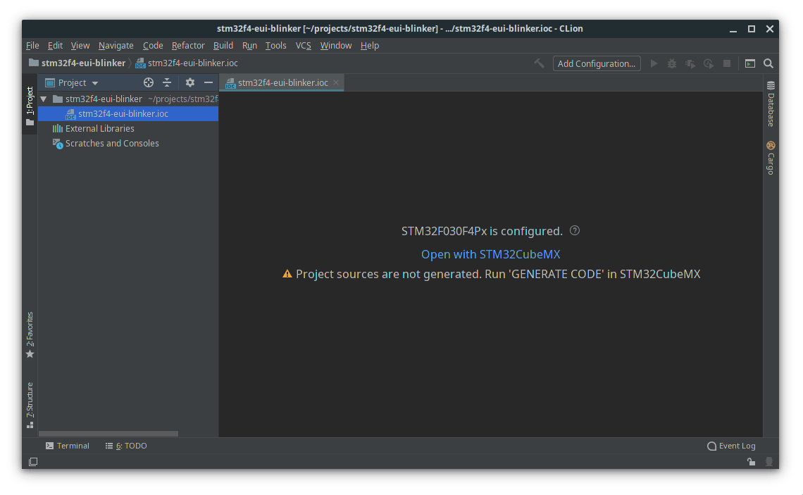
The template doesn't start with our target microcontroller selected, clicking the name of the microcontroller in the top breadcrumb bar next to "Home" will take you to the device selection page.
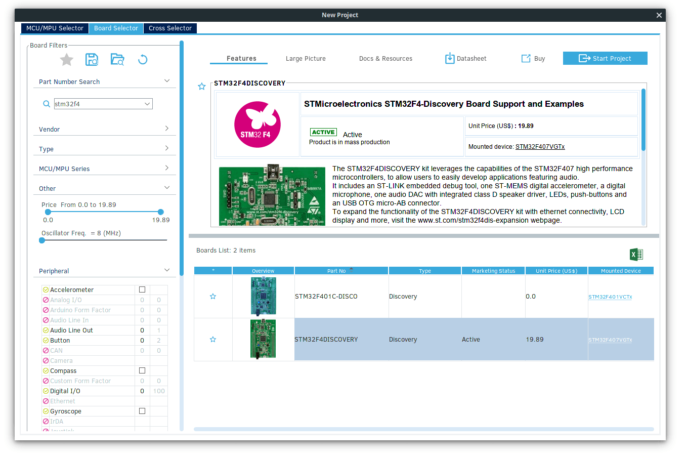
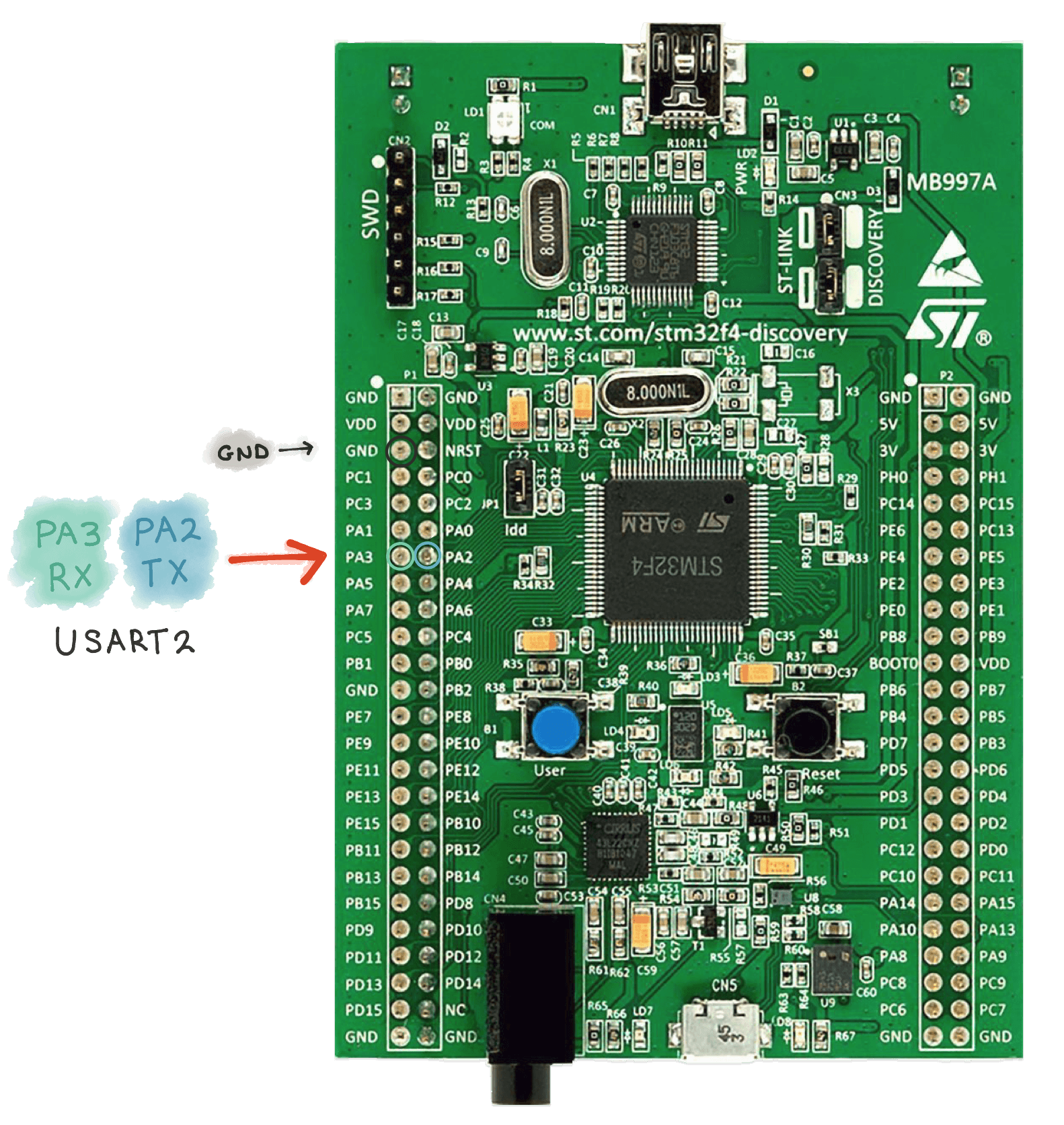
Find your microcontroller or development board. This article will use the trusty STM32F407 Discovery Board. In this example, we'll be setting up ElectricUI to operate over USART2 which corresponds to pins PA2 and PA3.
If you are selecting a board rather than a bare microcontroller, CubeMX will prompt if the peripherals should be configured in their default mode. This is useful to skip manually setting up GPIO for the user button and LEDs.
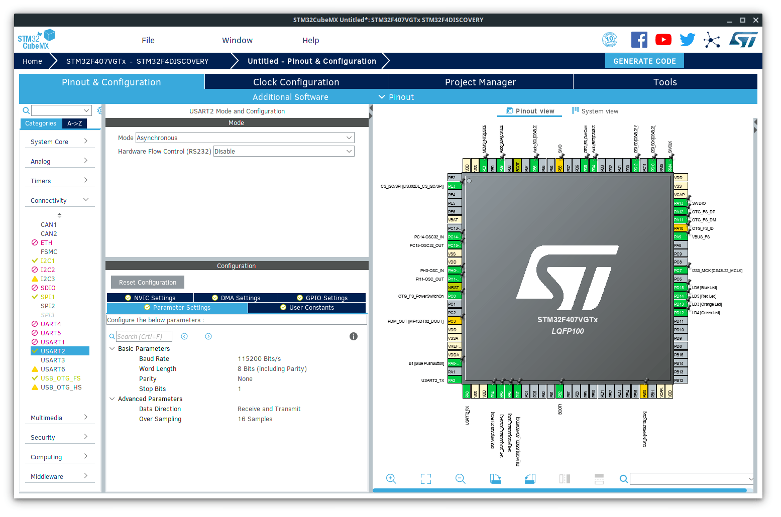
With the "Pinout & Configuration" tab open, we'll expand the "Connectivity" pane, and then select USART2.
Set the mode to Asynchronous, and check that the baud rate is set to 115200 Bits/s, with 8-bit word length, no parity, and 1 stop bit.
In the "NVIC Settings" tab, enable the USART2 global interrupt.
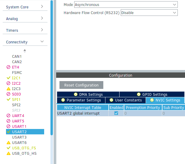
The hardware serial peripheral is now configured.
In the "Project Manager" tab, we need to re-configure the Project Settings as the microcontroller change effectively created a new file. Set the Project Name, Project Location to match the existing file created by CLion, and set the Toolchain / IDE dropdown to SW4STM32.
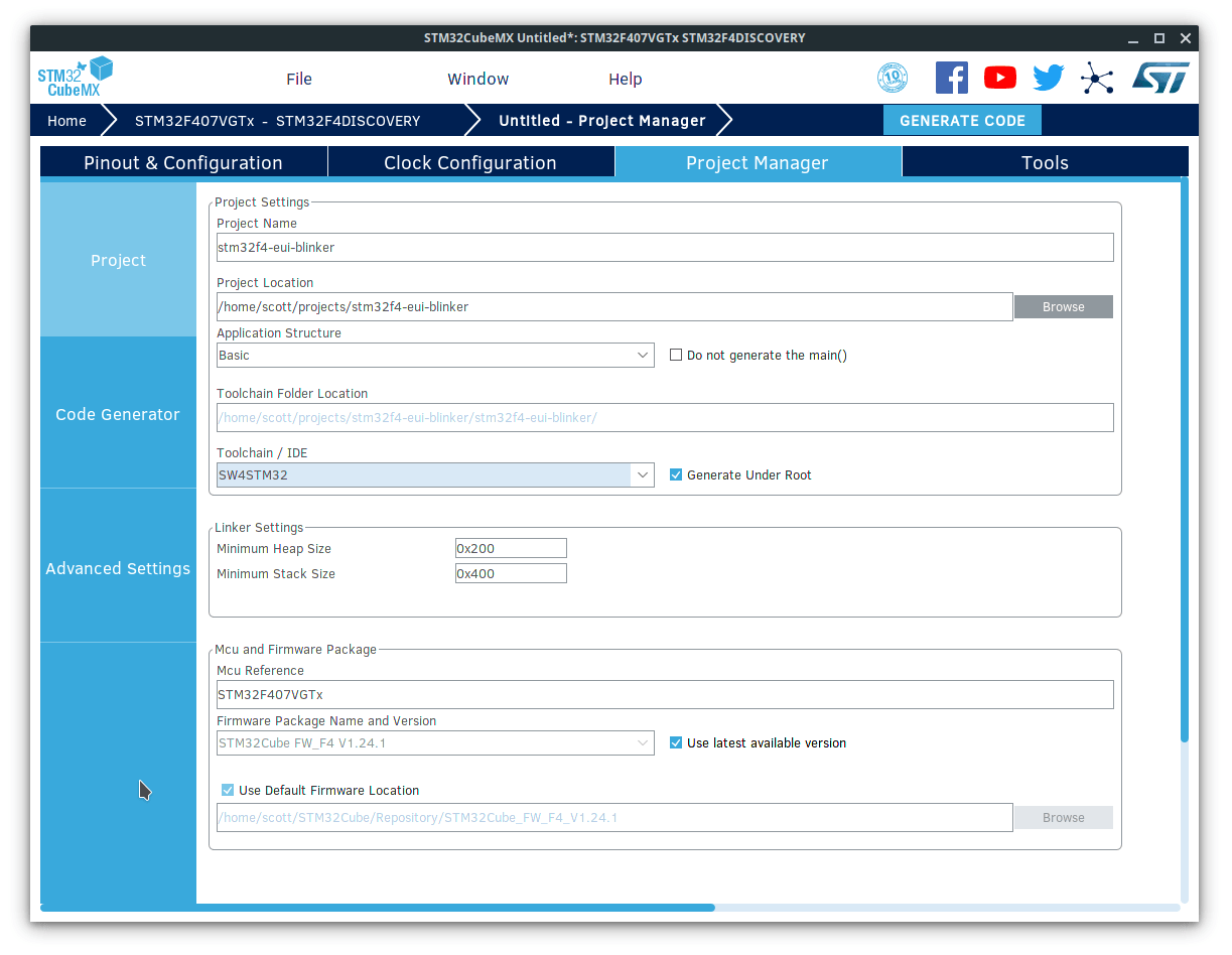
I also recommend clicking the "Code Generator" settings tab, and selecting the Generate peripheral initalization as a pair of '.c/.h' files per peripheral box, as it makes the generated project structure easier to manage in the long-run.
Remember to save your CubeMX project, then generate the code with the "Generate Code" button on the right side of the top toolbar.
CLion will detect the new files and update the project to match. When prompted, choose the relevant OpenOCD board config file to use for flashing rules. For bare microcontrollers, the config files for development boards of the same family often work fine.
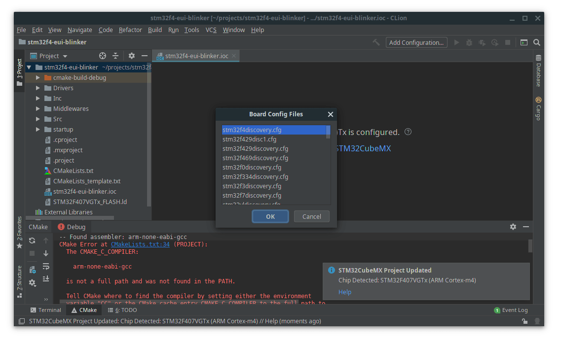
Issues with development toolchains can be painful to sort out when things don't just work.
- Make sure you have the gcc-arm-none-eabi compiler set installed on your computer.
- Make sure you can reach
gcc-arm-none-eabi-gccandgcc-arm-none-eabi-g++from your shell.- Configure these in CLion.
File > Settings > Build, Execution, Deployment > Toolchains > ...- Restart CLion (it needs to re-source), though I ultimately needed to restart entirely before the toolchains were found properly.
- Failing the above, you could attempt a ritual sacrifice.
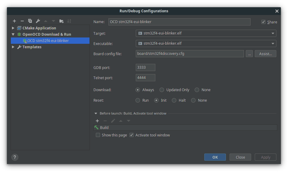
Once you are able to build the templated project successfully, configure the debugger from Run > Edit Configurations.
In main.c, add a LED blinker inside the superloop, then flash to your hardware to make sure everything works fine.
LD3 is the orange LED on the F4 Discovery board, and the port and pin naming is provided by the CubeMX template.
while (1){ HAL_GPIO_TogglePin( LD3_GPIO_Port, LD3_Pin ); HAL_Delay( 100 ); /* USER CODE END WHILE */ /* USER CODE BEGIN 3 */}If the selected OpenOCD
.cfgdoesn't find your STLink, try other OpenOCD configurations which match your platform. In my case,stm32f4discovery.cfgdidn't work whilest_nucleo_f4.cfgdid.The difference was the STLink version OpenOCD was trying to find. If desired, you can modify the
source [find interface/stlink-v2-1.cfg]line to match your board's programmer version.In some cases (very old unused Discovery boards) you might need to run newer STLink firmware version. You can update using the STLink update utility (java tool).
Now the development and debugging environment is setup, we'll configure our template to read and write serial data over the USART2 peripheral.
Setting up USART
We'll start by implementing a circular buffer which holds data as the usart interrupts fire. This means we can poll the buffer whenever we want, while new data is inserted as soon as new data arrives.
In usart.c, we'll be adding some functions to make life a little easier. To start with, lets declare the variables we'll need.
#include "usart.h"/* USER CODE BEGIN 0 */#define CIRCULAR_BUFFER_SIZE 32uint8_t rx_buffer[CIRCULAR_BUFFER_SIZE] = { 0 };uint8_t rx_head = 0;uint8_t rx_tail = 0;uint8_t rx_byte[2] = { 0 }; // buffer we give to the ST HAL/* USER CODE END 0 */At the end of the MX_USART2_UART_Init function call, we'll tell the HAL that we want inbound data to be put in our rx_byte variable, and we want it to fire the interrupt for every byte.
HAL_UART_Receive_IT(&huart2, rx_byte, 1);Now lets implement our circular buffer and grab data when the receive interrupt fires. We'll add this code to the bottom of usart.c in the templated user code area.
/* USER CODE BEGIN 1 */void uart_write(uint8_t *buffer, size_t len){ HAL_UART_Transmit(&huart2, buffer, len, 100); // 100 tick timeout}uint8_t uart_check_buffer(void){ uint8_t bytes_in_buffer = 0; // When the head and tail of the circular buffer are at different point we have data if((rx_head != rx_tail)) { // Handle data wraps across the buffer end boundary if( rx_head < rx_tail) { bytes_in_buffer = rx_head + (CIRCULAR_BUFFER_SIZE - rx_tail); } else { bytes_in_buffer = rx_head - rx_tail; } } return bytes_in_buffer;}uint8_t uart_get_byte(void){ if(rx_tail == CIRCULAR_BUFFER_SIZE) { rx_tail = 0; } return rx_buffer[rx_tail++];}// Callback on inbound byte, copy the data to the circular buffervoid HAL_UART_RxCpltCallback(UART_HandleTypeDef *huart){ if (huart->Instance==USART2) { if(rx_head == CIRCULAR_BUFFER_SIZE) { rx_head = 0; } rx_buffer[rx_head++] = rx_byte[0]; HAL_UART_Receive_IT(&huart2, rx_byte, 1); }}/* USER CODE END 1 */You'll need to put the function prototypes into the usart.h header so they are accessible from our main loop.
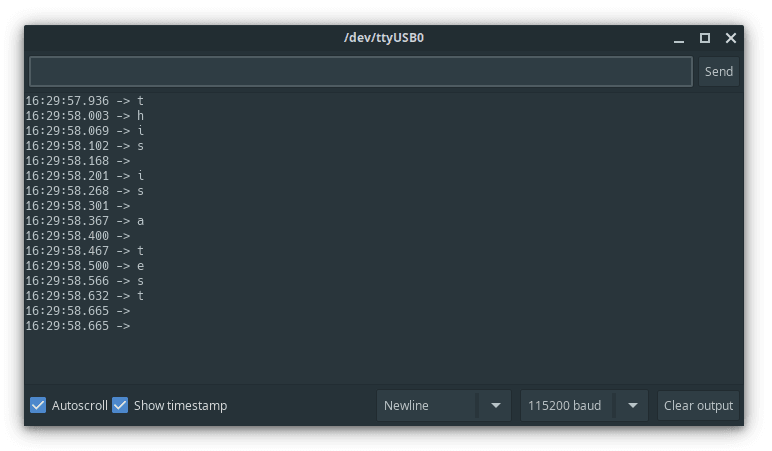
/* USER CODE BEGIN Prototypes */void uart_write(uint8_t *buffer, size_t len);uint8_t uart_check_buffer(void);uint8_t uart_get_byte(void);/* USER CODE END Prototypes */From our infinite loop inside main() we'll check if there is data, then write any data back over the serial connection for a loop-back test. Each inbound byte will be written to a new line, and due to the delay in our loop, we can watch them come back one by one.
/* Infinite loop */ /* USER CODE BEGIN WHILE */ while (1) { HAL_GPIO_TogglePin(LD3_GPIO_Port, LD3_Pin); HAL_Delay(50); uint8_t data_rx = uart_check_buffer(); if( data_rx ) { // Read the byte into a small printing buffer and append a newline uint8_t loopback[2]; loopback[0] = uart_get_byte(); loopback[1] = '\n'; uart_write( loopback, 2); HAL_GPIO_WritePin(LD4_GPIO_Port, LD4_Pin, GPIO_PIN_SET); } else { HAL_GPIO_WritePin(LD4_GPIO_Port, LD4_Pin, GPIO_PIN_RESET); } /* USER CODE END WHILE */ /* USER CODE BEGIN 3 */ }Opening up a serial terminal and we can see that inbound data is written back to us line by line (timestamps were added by the terminal).
We've now got the ability to send data over serial, store it as it comes in, then process it in our own time outside the interrupt.
Integrating Electric UI
First, use git to clone a copy of the electricui-embedded library, or download it from Github and unzip it.
Configure CMake to include the library by adding include_directories(electricui-embedded/src) to the CMakeLists.txt file.
Because the CLion embedded template uses the CMake
GLOB_RECURSEduring the file search on the default CubeMX directories, its a minor annoyance to add cleanly.Either put the directory into
/srcor/Middlewaresdepending on taste and deleteexamplesandtestfolders,... or ...
Place it elsewhere and explicitly add
/electricui-embedded/src/*.*to thefile(GLOB_RECURSE SOURCES "startup/*.*" ... "electricui-embedded/src/*.*")
In main.c, we'll include the embedded library, define a macro to help grab the STM's internal chip UUID, and declare some variables for a adjustable LED blinker demo.
#include "electricui.h"#define STM32_UUID ((uint32_t *)0x1FFF7A10)uint8_t blink_enable = 1; //if the blinker should be runninguint8_t led_state = 0; //track if the LED is illuminateduint16_t glow_time = 200; //in milliseconds// Timestamp used as part of LED timing behaviouruint32_t led_timer = 0;char nickname[11] = "STM32 UART"; // human friendly device nameCreate a function which accepts a pointer to a buffer of uint8_t, and the corresponding length of data. This callback will be provided to Electric UI to use when it needs to send data to the UI.
void eui_serial_output( uint8_t *data, uint16_t len){ uart_write(data, len);}Now, lets setup the eui_interface_t which represent the hardware interfaces we'll be using to communicate with the user interface.
// Instantiate a communication interface management objecteui_interface_t eui_comm = EUI_INTERFACE( &eui_serial_output );We want the user interface to access the variables we declared as part of our LED blinker. Simply create an array containing eui_message_t for the variables you want to track. Electric UI provides a series of macros which reduce the boilerplate involved.
For each tracked variable, we use the macro which corresponds to the type of the data being tracked, include a message identifier string, and then the reference to the variable.
// Electric UI manages variables referenced in this arrayeui_message_t tracked_vars[] ={ EUI_UINT8( "led_blink", blink_enable ), EUI_UINT8( "led_state", led_state ), EUI_UINT16( "lit_time", glow_time ), EUI_CHAR_RO_ARRAY( "name", nickname ),};At startup, we need to tell Electric UI about the interfaces available, the array of variables to manage, and the identifier for this specific board. We'll put these calls inside main() just after the HAL setup is called (MX_USART2_UART_Init() etc).
/* USER CODE BEGIN 2 */eui_setup_interface( &eui_comm );EUI_TRACK( tracked_vars );eui_setup_identifier( (char *)STM32_UUID, 12 ); // 96-bit UUID is 12 bytesled_timer = HAL_GetTick(); //bootstrap the LED timer/* USER CODE END 2 */Now our setup is done, we just need to pass data into eui_parse as it comes in.
Then, we have some simple code to control the orange LED blinker.
/* Infinite loop */ /* USER CODE BEGIN WHILE */ while (1) { while( uart_check_buffer() ) { eui_parse(uart_get_byte(), &eui_comm); } if( blink_enable ) { // Check if the LED has been on for the configured duration if( HAL_GetTick() - led_timer >= glow_time ) { led_state = !led_state; //invert led state led_timer = HAL_GetTick(); } } HAL_GPIO_WritePin(LD3_GPIO_Port, LD3_Pin, led_state); // set the orange LED /* USER CODE END WHILE */ /* USER CODE BEGIN 3 */ }That's it! Compile and flash to the board, and fire up a fresh Electric UI template project to test it in action.