Building a Delta Robot
Scott
Light painting with CNC precision, designed for practical hologram effects in animation.
Motivation
The idea first came up while Michael and I were discussing stopmotion techniques used for physical animation, and examples such as BEARS ON STAIRS and the Penki light-painting app came up as interesting applications of accessible hardware.
The idea of being able to create a high fidelity 'hologram' akin to the persistence of vision displays, but with resolutions more suited for artistic use. This led to the conceptualisation of a light painting robot.
Getting to design new kinds of hardware and motion control software always presents lots of new toys to play with.
Planning
It wouldn't be wise to commit much to an ambitious hobby project like this without a quick requirements analysis.
- Needs a starting work volume of approximately 500x500x500 mm or so (prototypes can be smaller),
- Reasonably high precision (around 1/4 diameter of the light source),
- A starting effective 'resolution' of a couple hundred 'voxels' in each axis,
- the ability to 'render' a reasonably complex scene in a short period of time (as 30fps animations would take weeks for seconds of footage otherwise),
- High repeatability to reduce warping/skew or offset errors between 'frames',
- Reasonably easy to move into new environments, (transportable in a car, single person lift),
- Doesn't have a frame that will occlude light when trying to shoot from other angles
While I conceptualised different design concepts based on SCARA arms, cartesian gantry setups, and cable-drawn movement systems, I settled on a rotary delta robot design.
Delta robots are most commonly found in industrial applications for pick and place and fast moving low-mass tasks. They actuate with 3 rotating joints (shoulders) which have a parallel linkage to the end effector (toolhead). Some include an optional link through the centre to allow for tool rotation.
Some examples of existing delta robots include systems from Fanuc and ABB.
This style of design differs from the typical linear delta 3D printer, as it trades vertical volume for the removal of vertical columns. There are quite a few DIY deltabots on youtube, in both hobby and university projects, but a majority use RC servo's, open loop control, and insufficiently stiff frames. This mean some many produce results like this.
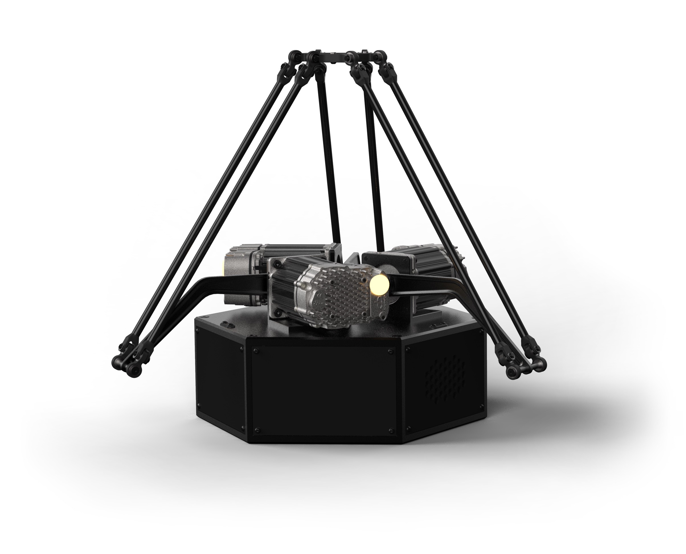
For bench use and general testing, along with the animation concepts planned for the first uses, this delta would point upwards, which is a little unconventional. At a later date, I might design a rig to suspend it.
Mechanics
As I was intending the delta for a nearly zero-mass payload, and focusing on a robust desk-based design, I elected to use a combination of carbon tube and carbon plates, CNC aluminium base plates and structure, and 3D printed linkages for the first prototypes.
The DeltaBot consists of 3 distinct 'assemblies':

- Arms, linkages and end effector
- Top plate with motor mounts and motors
- Bottom frame assembly, with PCB, power supply, cooling and connectors
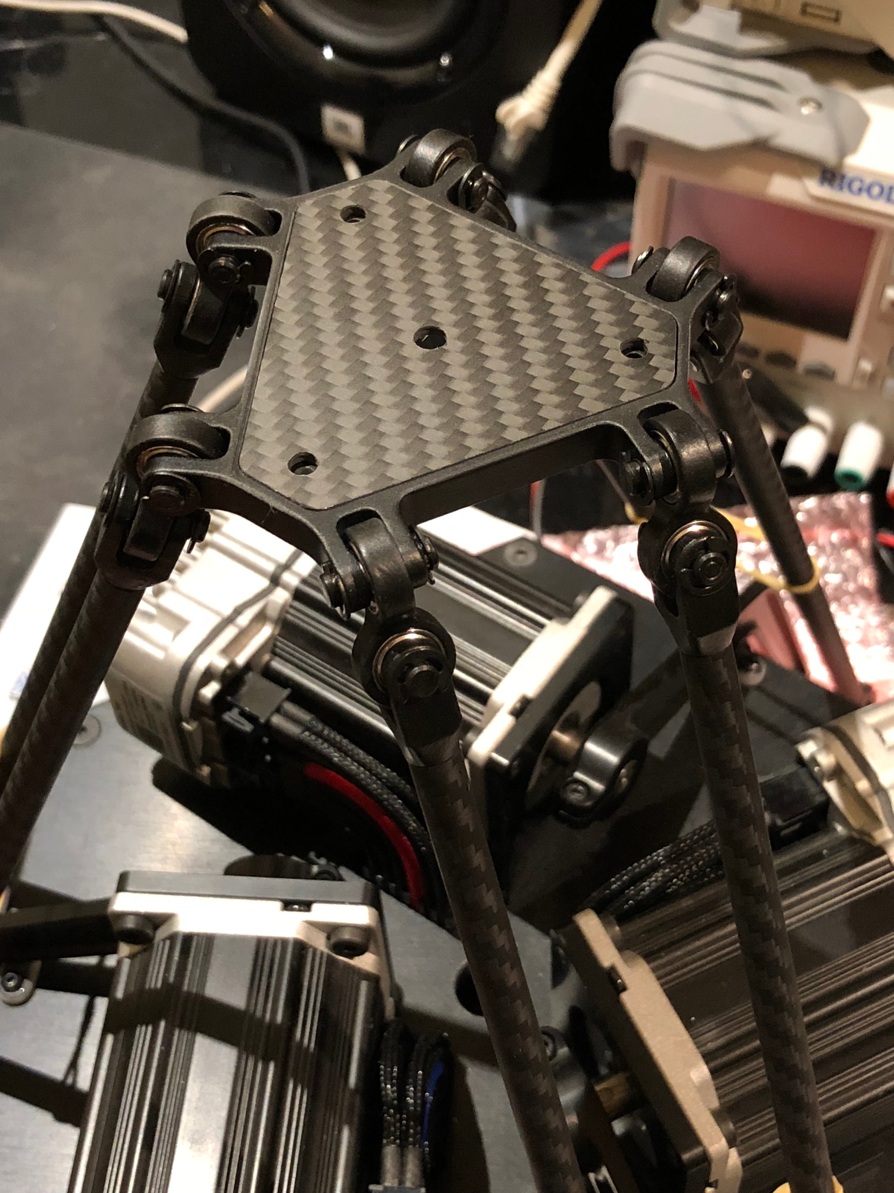
Arms and End Effector
The main mechanism builds around custom universal joints which run SB685ZZ bearings and 4mm shoulder bolts. This system is meant to provide lower backlash/slop than integrated rod-end solutions such as the IGUS KAIM products, or ball-and-socket style found more commonly on industrial deltas. The magnetic ball joints commonly seen on linear delta printers weren't considered.
The tolerances for affordable off the shelf ball or rod-end joints aren't the greatest, and have a limited range of motion. The universal joint approach is also seen in some linear deltas used for 3D printing.

Python and matplotlib helped visualise the mechanics of the bot, this provides a check that the kinematics works as expected, and allows for more comprehensive checks of angular ranges and achievable work areas..

The work area shows the possible reachable areas, we aren't interested in the extreme areas near the tip, or the corners around the motors. From memory, the intended cartesian work area was ~280x280x300 mm, but the lengths of the arms did change a little since the first concepts.

The code for the python test is available on Github
Motor Selection
While most DIY builds online use RC servos or sometimes stepper motors, we wanted to use brushless servo motors with a high resolution encoder. Industrial drives offer a level of precision and speed which is typically hard to match with hobby grade RC servo motors.
I've used the Teknic Clearpath motors on work projects and have been wanting to use them on a personal project for a while. They are a compelling choice due to NEMA 23 mount, integrated drive electronics, and simplified control strategy (they self-manage & auto-tune the control system).

While the Clearpath servo's aren't as cheap as building a drive from scratch (from a parts cost perspective), or as affordable as some of the lower cost competing options for hobby use like ODrive, Mechaduino, or dynamixels, Clearpaths are more mature, have rugged housings and heatsinking solutions, operate on a far wider voltage range, have access to more torque, and are more suitable for reuse with other CNC applications in the future. I want to build the delta, not spend chunks of time developing or modifying drive systems.
I selected their stepper style servos as they offer a traditional step/direction input. I've had issues with complex motion handling on the PV and SC families on other projects, and using a SD model means the software should port to a conventional stepper driver without too much pain.
No NEMA 17 Clearpath options exist, so the design builds around NEMA 23 options (34 is way too large), and I then sorted by cost and created a small comparison table.
| Servo Model | Peak Torqe (oz-in) | RMS Torque (oz-in) | Cost (USD) |
|---|---|---|---|
| 2310S | 223 | 44.9 | 257 |
| 2311S | 290 | 58 | 279 |
| 2321S | 492 | 98.3 | 299 |
| 2331S | 620 | 124 | 319 |
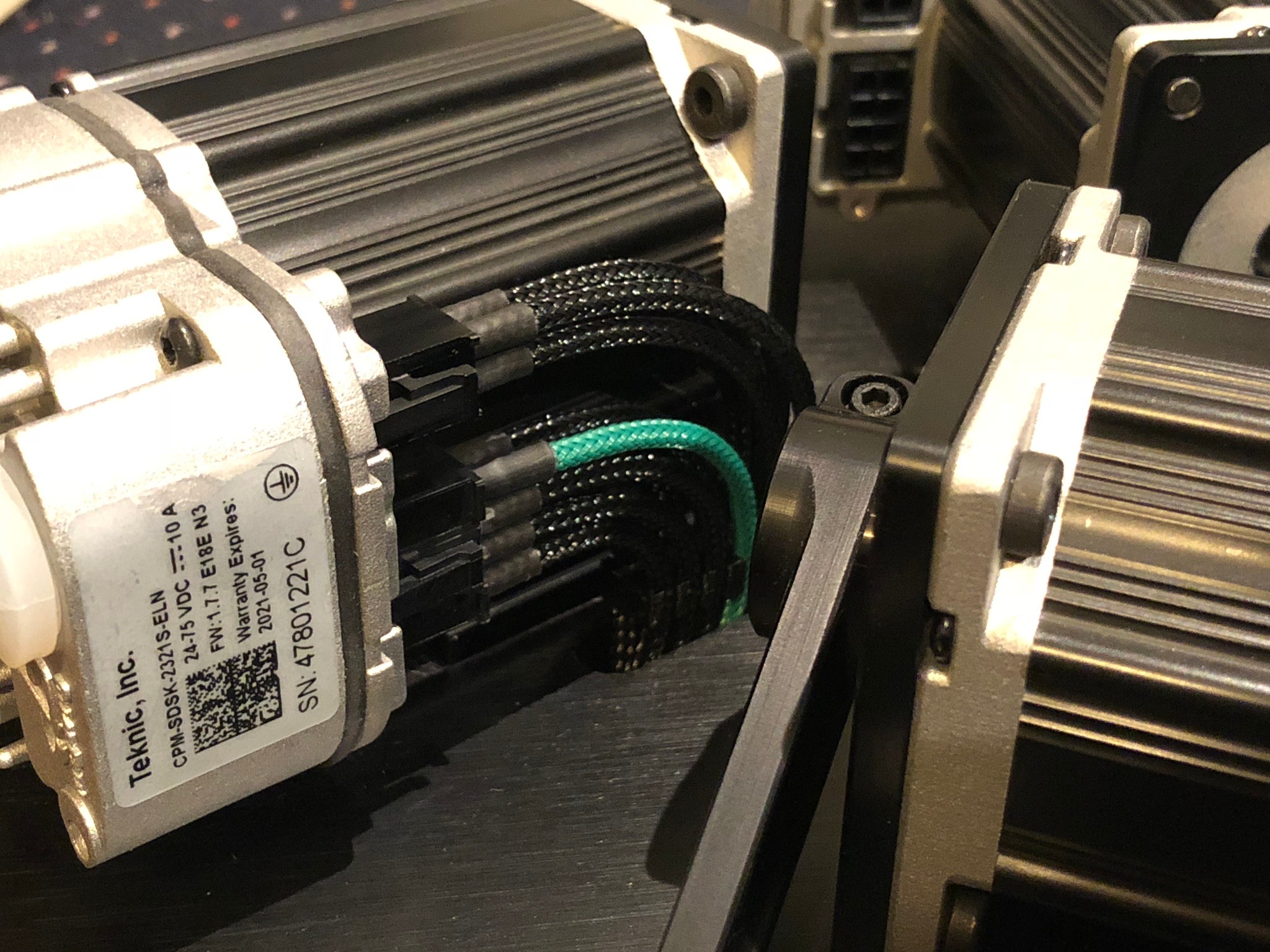
The final selection was the CPM-SDSK-2321S-ELN. Getting the enhanced option (E variant, +$50ish) is important to expose 6400-count positioning control, as the base motors have a limited 800-angular-counts control resolution. They are over-specced for the application as the freight, taxes and tariffs into Australia are hefty, so these should be suitable for other uses later on.
At some point in the future, I may add some small reduction gearboxes to increase the precision and torque, but finding compact and affordable options with low backlash wasn't easy, so for now I can get the system running in a direct drive setup.
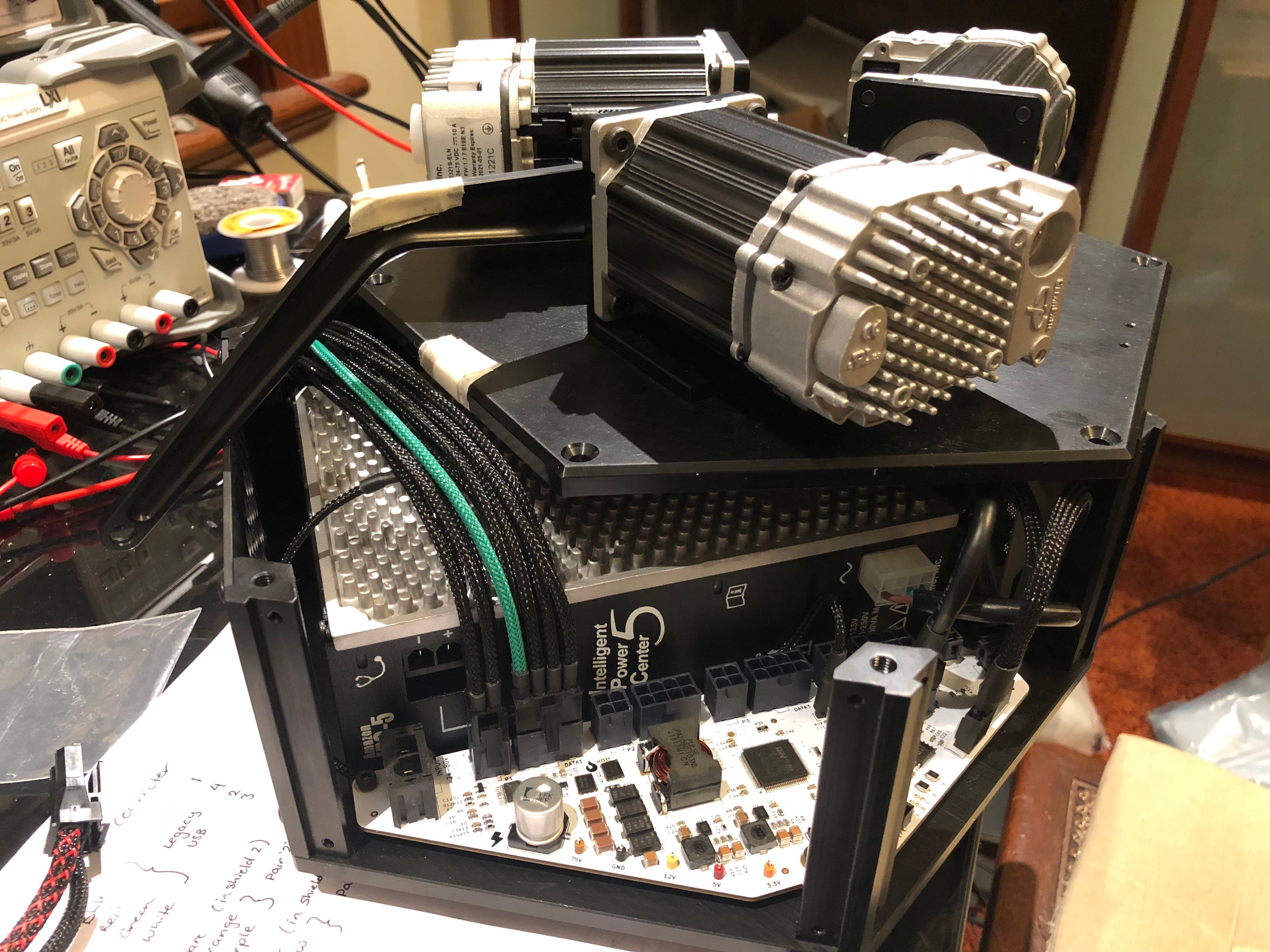
Motor Mounting & Base Structure
The base follows a hexagonal design with pillars to form the main structure. Carbon side plates would provide reasonably stiff mounting surfaces and are pretty easy for me to route with local contacts or offshore services.
The Clearpath power supply sets the internal sizing requirements, with minimal clearances to support the cooling fan and mains input connector. Top and bottom frame plates featured pockets for weight reduction (1.2kg per solid plate, reduced to 580g). A carbon floor plate on the bottom adds mounting flexibility and should limit dust ingress mounting holes.
The motors mount to the top hexagonal plate on angled brackets, positioned so the end of the shaft would act as a rough locating feature for the biceps. By installing them sideways, power and control wiring could loop through the top plate with little chance of catching on the mechanism or people.
In hindsight, a different design could remove the bottom section of the angled mount. A gusseted design perhaps...
Version 1 Mechanics
The core of the design was complete, and looked something like this...

Quotes for parts were sent out and orders made over the following weeks while the PCB design was completed.
Electronics
Ideally the motor and end effector electronics, along with power supplies and processing would be housed inside the base of the unit. I also didn't want to rely on high performance compute modules like the Raspberry Pi or ODroid platforms for motion planning or GCODE execution like the systems commonly developed for 3D printers.
The Clearpath motors run best on a 75V supply, and would need about 200W for the motion I was planning. The Teknic IPC-3 was originally specced, but I ended up using an enclosed IPC-5 unit as they are common with previous units I've used.
A custom control PCB provides power, IO, and management of the motors. It uses a STM32F429 processor.

The board was developed with KiCAD, and has the following features:
- 13-80V input voltage range
- Onboard regulator for 75V -> 12V @ 5A
- 3.3V and 5V regulators with 1A capability
- Connectors and power distro for 4 Clearpath servos
- Current measurement for each servo's supply
- Ample expansion IO for internal and external use
- Onboard and expansion temperature monitoring
- PWM fan drive circuit
- Fully isolated USB connection
- Fully isolated external IO lines
- Two user buttons and three LEDs for status output
- Support for an onboard add-on module for wifi/bluetooth in the future with USART
Software Overview
Typically software becomes the most complex and time consuming aspect of my projects.
Fortunately, the PCB is actually pretty simple and doesn't require any complex drivers for sensors etc.
In general use, the main loop sleeps wherever possible, waking on interrupt (with a 1ms systick timer being the most frequent). At this point, the background processes run, and a task from the queue executes.
| Grouping | Description |
|---|---|
| app_state_machines | HSM structured higher level logical tasks. Subscribe and emit events. Only allowed to interact with drivers. |
| drivers | Simpler self-contained modules, some contain a simple-state-machine implementation. Typically manage hardware, convert sensors to quantities etc. |
| hal | Hardware abstraction to interact with specific peripherals or microcontroller functions. |
| utility | Helper code which forms the backbone of the statemachines, or some other generic behaviour (fifo, queues, state machine macros). |
HAL
Interacts with the hardware on a lower level. This may be direct hardware register manipulation, or calls to a vendor HAL codebase.
The project uses the STM32 HAL. A generated project from CubeMX provides the base, which is then ripped away as my own driver layer replaces it. This helps when mocking for unit tests, and allows the painful parts of the ST HAL to be hidden behind a more sensible API layer.
This somewhat promotes portability between my projects as the HAL layer can provide abstraction for different hardware versions or include subtle changes for microcontroller variants as needed.
Drivers
Simpler blocks designed to operate statelessly or with a simple state machine and processing loop. These aren't handled by the task system, and aren't intended for overly complex logic.
A driver typically performs a role where interaction with the HAL layer is required, such as sampling a ADC, i2c sensor, or manage a PWM output, and typically provides human-friendly interactions with the underlying hardware.
From this point and upwards, sensor readings are converted into SI units for example, averaging/bounds/error detection is done at this layer.
Higher Level Tasks
This system uses a simplistic tasking system based on a hierarchical state machine structure (HSM), and provides event-driven state machines.
Code in these tasks runs on event driven stimuli, though often sub-states will start timers with the intent of returning to poll or change state.
For a given 'task', an arbitrary number of states can be defined (as functions), which contain a macro driven pattern for handling entries and exits from the state, and handling for external events.
Tasks are used for supervisory roles which require involvement from different subsystems or peripherals. One good example is the motion processing task, which calls down to the servo drivers, interfaces with the pathing engine, and handles inbound movements with a queue.
Kinematics and motion handling
The most relevant functions of the software are calculating the path the toolhead needs to traverse (in cartesian space), and then converting the target position to motor angles with inverse kinematics.
The motion task accepts inbound motion requests and handles a queue of movements, dispatching new movements to the pathing engine when the previous move completes.
The pathing engine accepts movements which contain information such as absolute or relative positioning modes, target execution duration of the movement in milliseconds, path type (line, quadratic beziers, cubic beziers, catmull-rom splines, etc), and a small list of points to define the line or curve.
It then calculates the target position based on a linear mapping between expected progress at the current time, and the percentage completion of the movement.
Global (x,y,z) positions in cartesian space are then sent from the pathing engine to the kinematics processor, which calculates the desired motor angles.
Each motor has it's own supervisor driver instance, and these are passed the target angle after the kinematics processing has been completed. The servo supervisor then instructs the motor to reach the target angle, and provides shaft velocity clamping and fault detection and handling.
Prototype
Printed Prototypes
I used this as an excuse to try out a Chinese SLA printing service instead of using my FDM printer, testing out some end effector geometries and linkage parts.

The quality (and price/speed) was fantastic, and these have become the current parts for the universal joints and effector for now. I painted the parts with a matte black spray paint to help them blend in with the rest of the carbon and aluminium parts.

In the future, I might consider making the universal joints and end effector out of aluminium to support higher mass/load payloads and reduce deflection.
Once the first prototype was made, the effector and the clevis joints were redesigned pretty quickly, favouring Misumi bearings and matching bearing pins, over Aliexpress bearings and shoulder bolts.
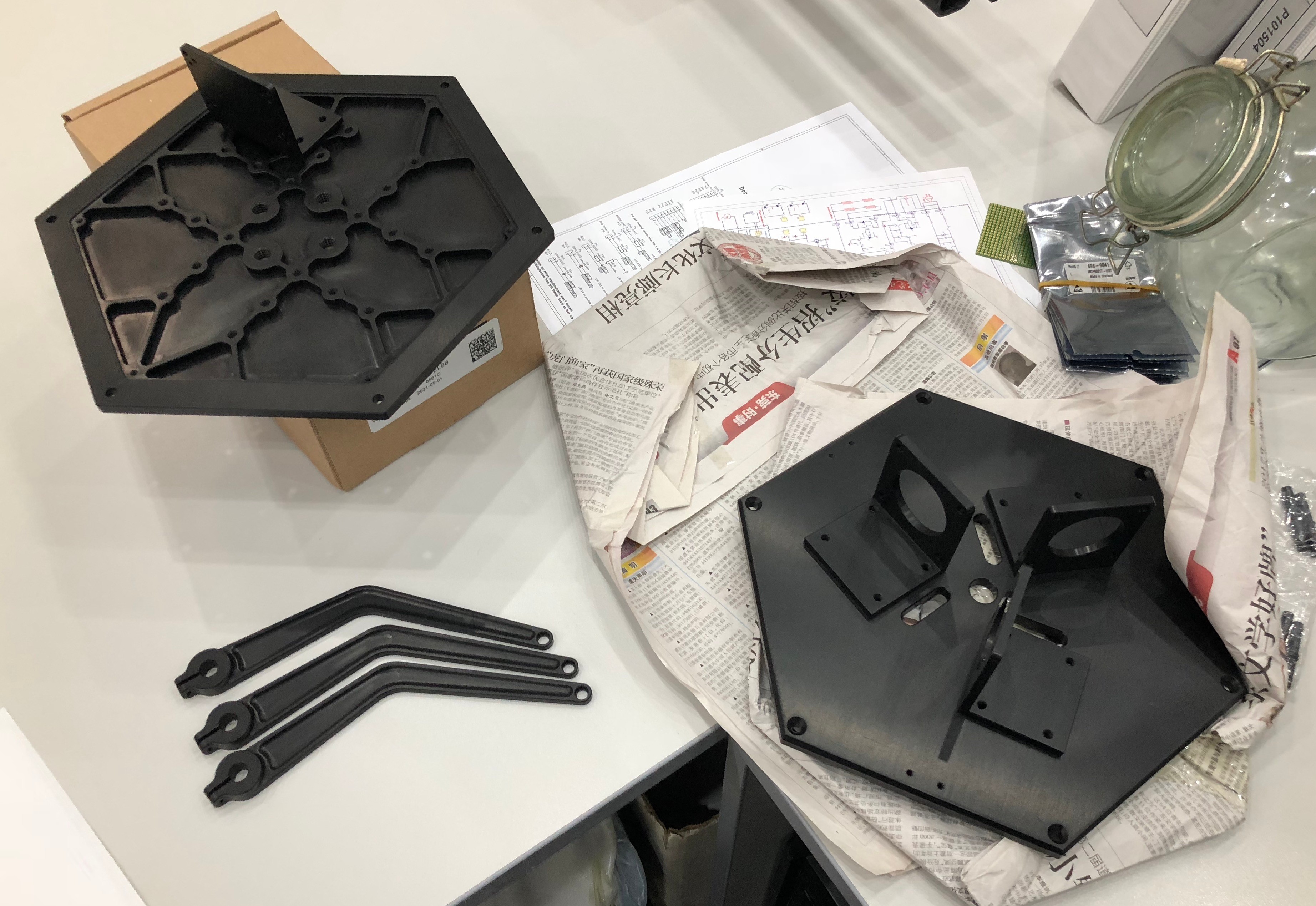
CNC Aluminium
Plates for the main structure, motor mounts, vertical pillars, bicep parts and vertical support pillars were CNC machined and matte black anodised in China.
The prices were ok and the work is to tolerance, but the chamfers seem to be hand machined or inconsistent in some areas, and I should have specified a finishing process prior to anodising as some machining marks show through.
Carbon Plates
Carbon side-plates protect users from the electronics, and hide the internal wiring. I use a larger plate as a false floor underneath the electronics to prevent dirt from entering through the mounting holes (and it looks pretty).

I also made an insert for the end effector to improve stiffness of the printed part.

PCB Manufacture
I took a gamble and tried a new supplier, HX Circuit. The board quality is pretty reasonable, they have pretty transparent quotes with regards to board cost and start fees, and the boards came with a thorough test report, a board which had suffered through wetting tests, and an epoxy encased board sliver to prove the layer stack and via plating quality.


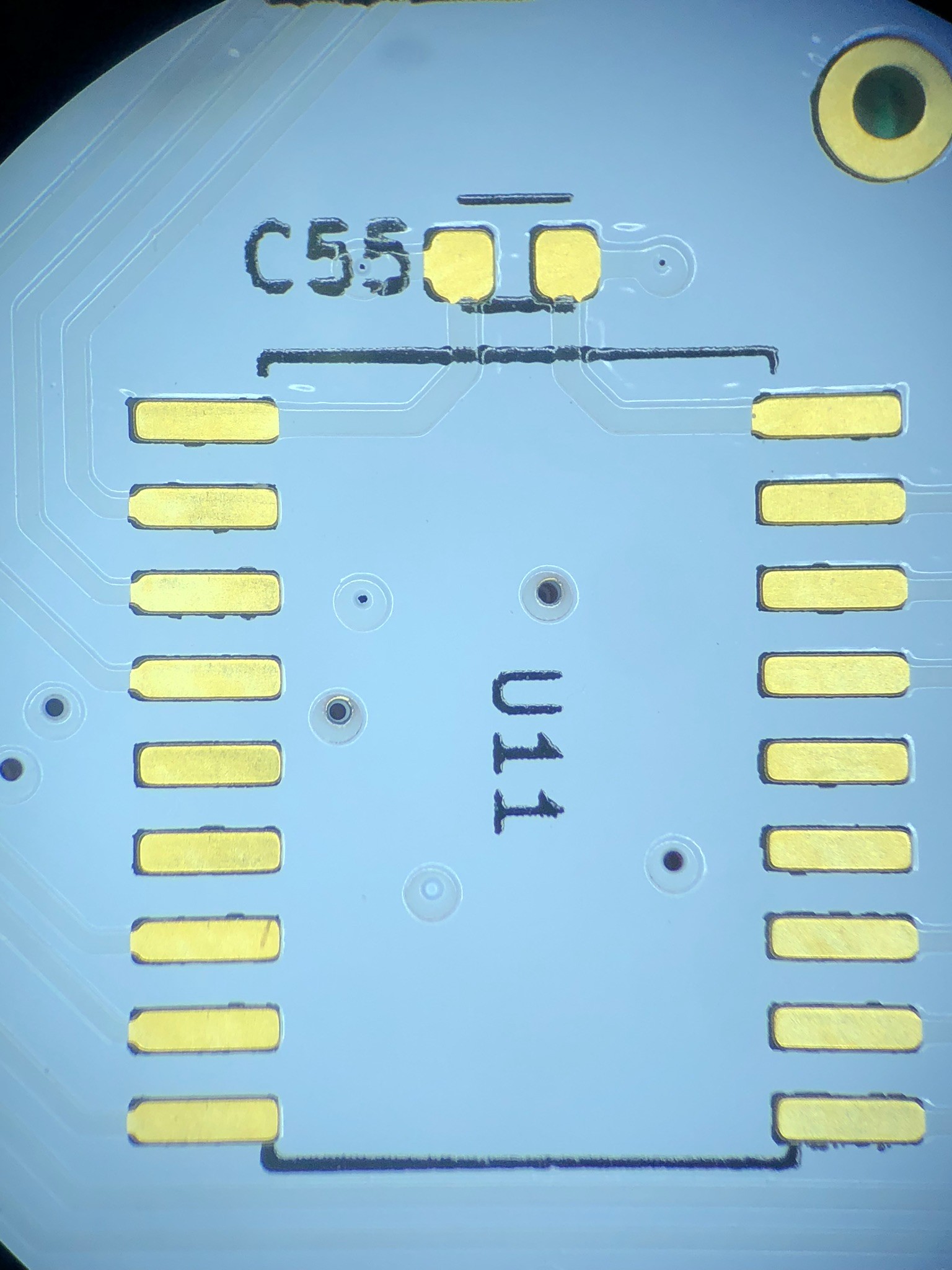
Top layer drill and copper alignment is pretty good, most fabs would inflate the soldermask clearances on the QFP, though we can see some vertical silkscreen alignment offset.
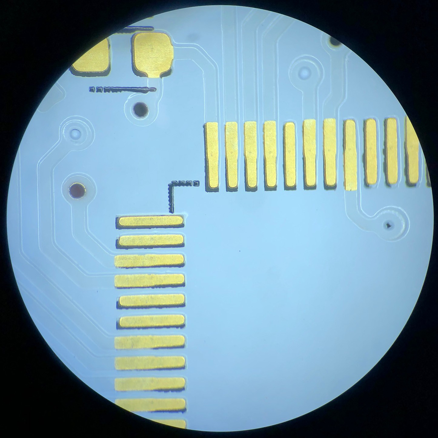
The bottom layer has better soldermask alignment, but silkscreen alignment has similar alignment issues to the top layer. You can see the pin 1 marking in the bottom right of U11 clips into the soldermask clearance zone. This could be mitigated with more forgiving pin 1 indication in the footprint (but I follow IPC-7351 so...)
I then hand populated the boards. This was a simple paste and electric skillet job for the top layer (STM32, regulators/FETs/inductor), and then paste with hot-air for the bottom layer (IO protection, darlingtons, buzzer).
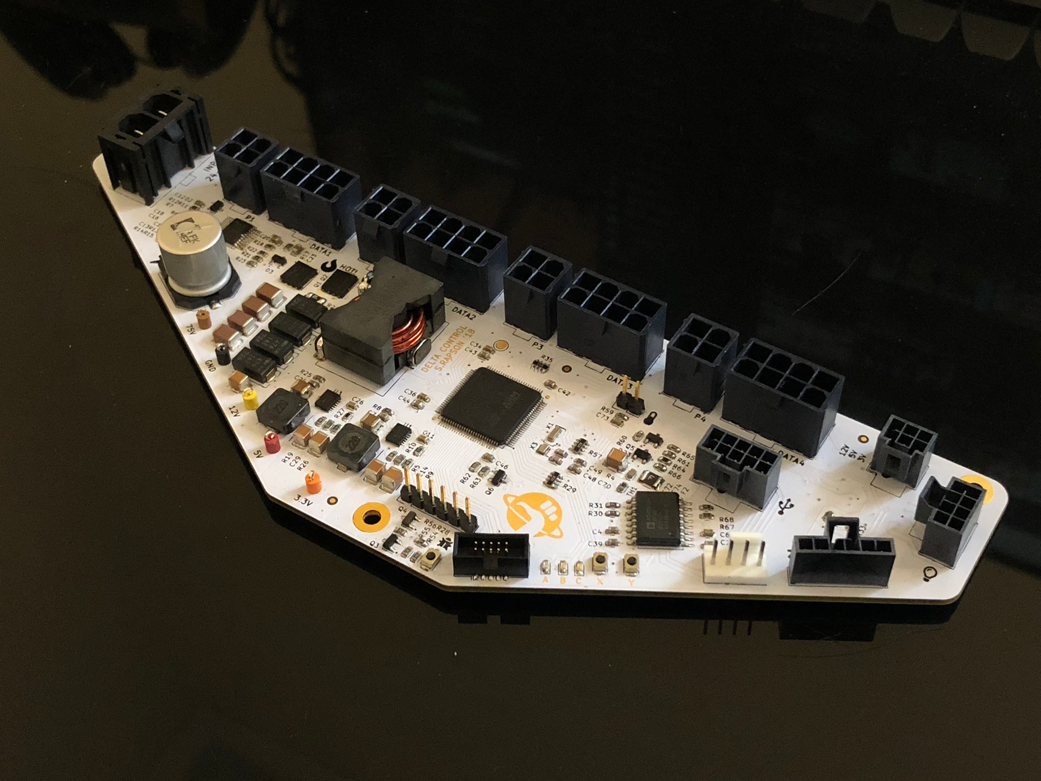
I'm reasonably pleased with the results, the white boards didn't yellow as much as I've seen in the past, and everything fits as intended. I'll probably use 2mm thick boards and move expansion IO connectors around if I end up needing to respin in the future.
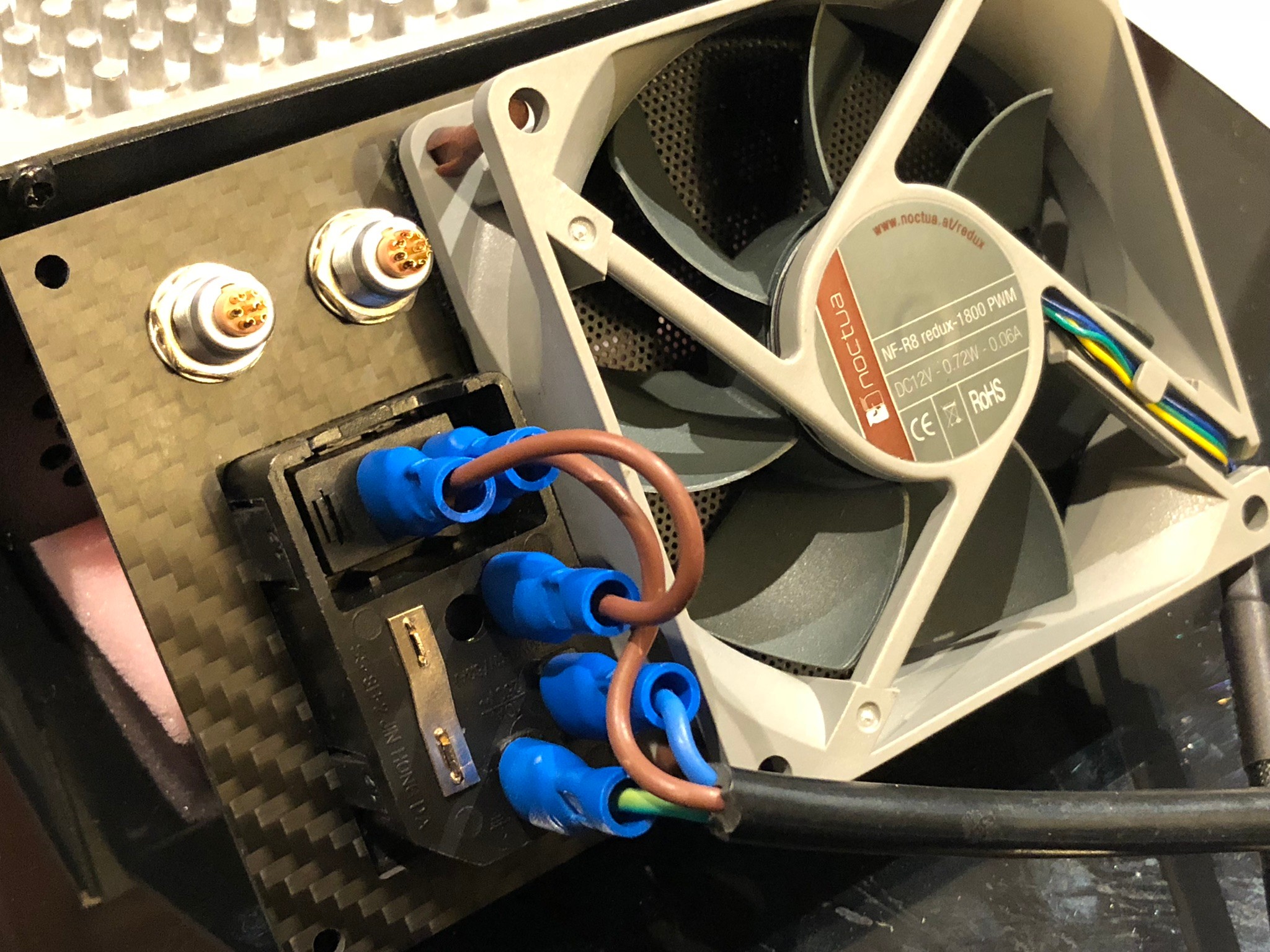
Wiring Looms
Wiring and connectors were hand crimped. This included re-terminating the fan cable, finding black mains cable, and spending way too long properly making the looms interfacing with the LEMO expansion connectors.
The 'LEMO' sockets and plugs came from Aliexpress and while they are likely clones, feel as good as genuine connectors I've used in the past (and tested as interoperable).
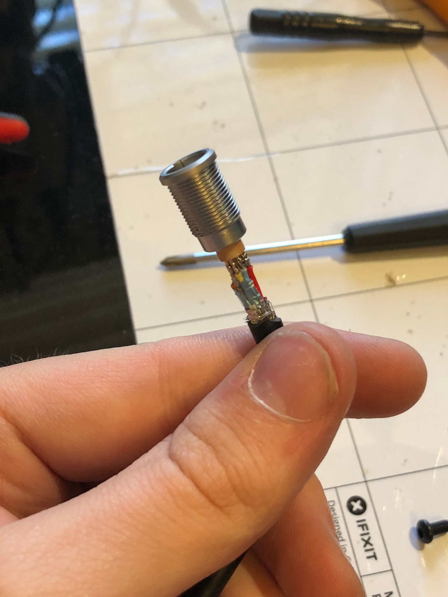
These connectors were one of the better ways to achieve the pin count and power density I needed to fit in the tight area above the mains input block. In the future, I'd purchase pre-wired connectors from another vendor like these ones as the slight cost difference is more than justified.
I also crimped the mains cable and installed the panel mount IEC connector to it's carbon plate, along with the fan.
Integration with Electric UI
Integration was reasonably straightforward, I opted to use git submodules to put the ElectricUI embedded repository into the 3rd party driver folder of the project.
Most of the integration occurs in a driver called configuration, which behaves like a singleton. It holds settings which the UI is able to read or write against, and getters and setters provide access to these structures throughout the rest of the firmware.
Centralisation of these values provides the configuration driver the ability to handle tasks like default resets, and save/load to flash.
For larger projects like this one, or in any situation where there are obvious logical groupings for variables, I prefer to create structures for a given set of variables, such as fan information or sensor data.
Passing these structures through Electric UI works seamlessly as long as the structure has a corresponding decoder on the UI side. This approach requires a little code on the UI side to handle, but feels less cluttered than a few dozen named messages.
Testing
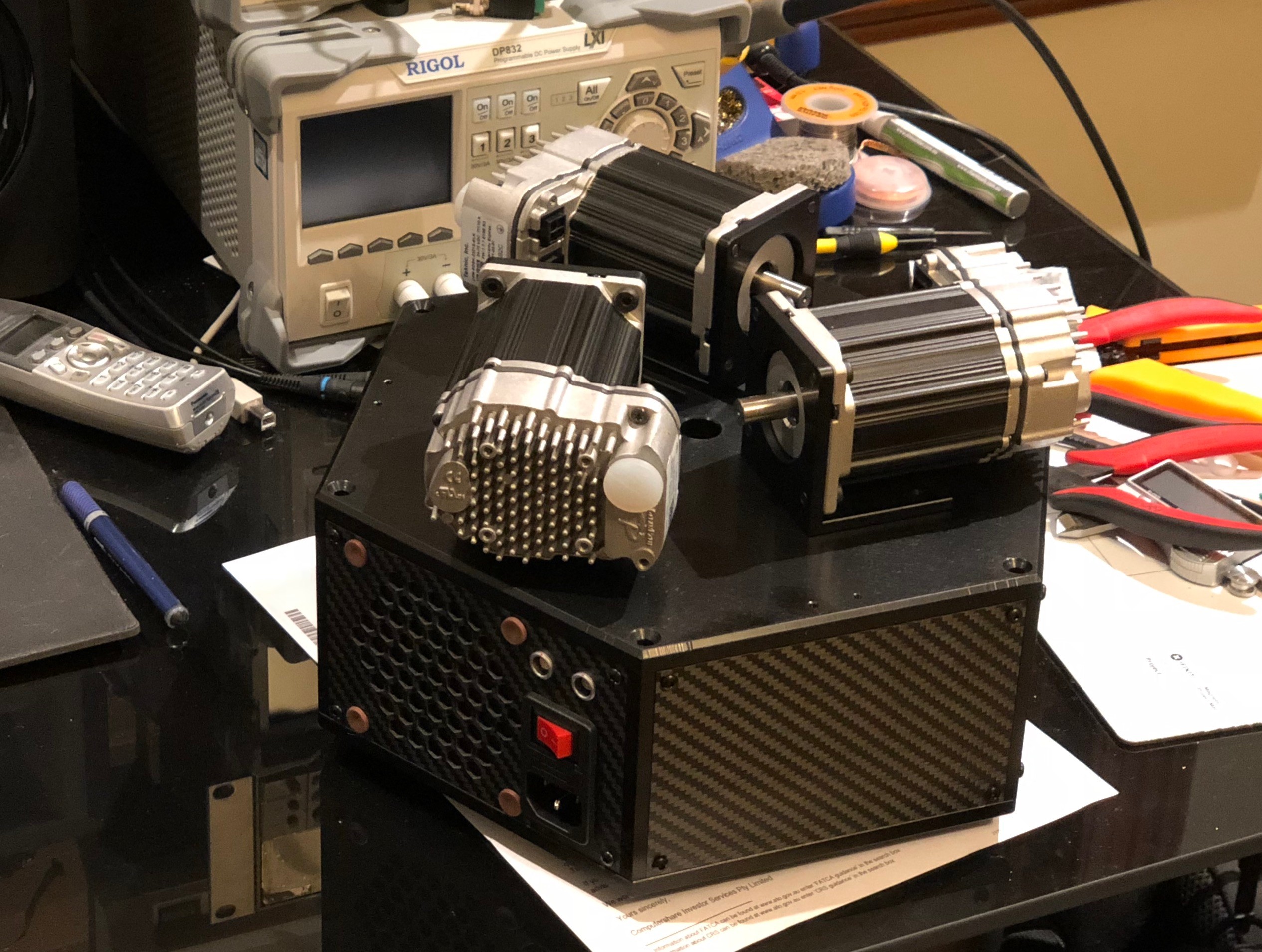
The initial test and hardware bringup process occurred as parts arrived, I had about a week and a half with partially assembled PCB's before receiving the CNC aluminum frame.
PCB Bringup
The PCB was partially populated to validate the 75V -> 12V regulator design, though testing only checked the 12-32V range due to the limits of my lab supply.
From there, I installed the 5V and 3.3V regulators to check the outputs weren't doing anything odd, and then installed the remaining parts and connectors.
Once the programmer could identify the microcontroller, quick tests checked the status LED, button inputs, ADC readings and servo IO worked as expected. I developed and tested a good chunk of the firmware at this point, using a scope to validate output motor commands, and function generator to simulate feedback from a servo. Fan handling was also fleshed out.

I caught an incorrectly placed octal darlington which handles motor IO, placed incorrectly due to an obscured pin-1 marking!
Servo Setup
The servo's were reasonably easy to test with power through a test loom. Connecting over USB and using the Clearpath MSP tool to setup torque limits, homing modes and perform tuning is pretty straightforward.
By pressing CTRL+SHIFT+P, an advanced tuning interface appears and provides tools to create repeating movements and tweak the servo tune manually.
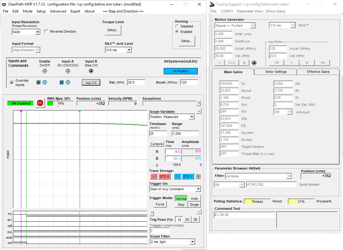
Results with a single bicep looked pretty good, so I rolled this configuration out to the 2 other servos, and started testing the firmware's handling of the servos by gradually enabling functionality.
Motion and performance testing
With the bulk of the hardware under control, motors working and homing correctly, the kinematics and pathing engines were tested (and iterated on) until things started moving in the expected manner.
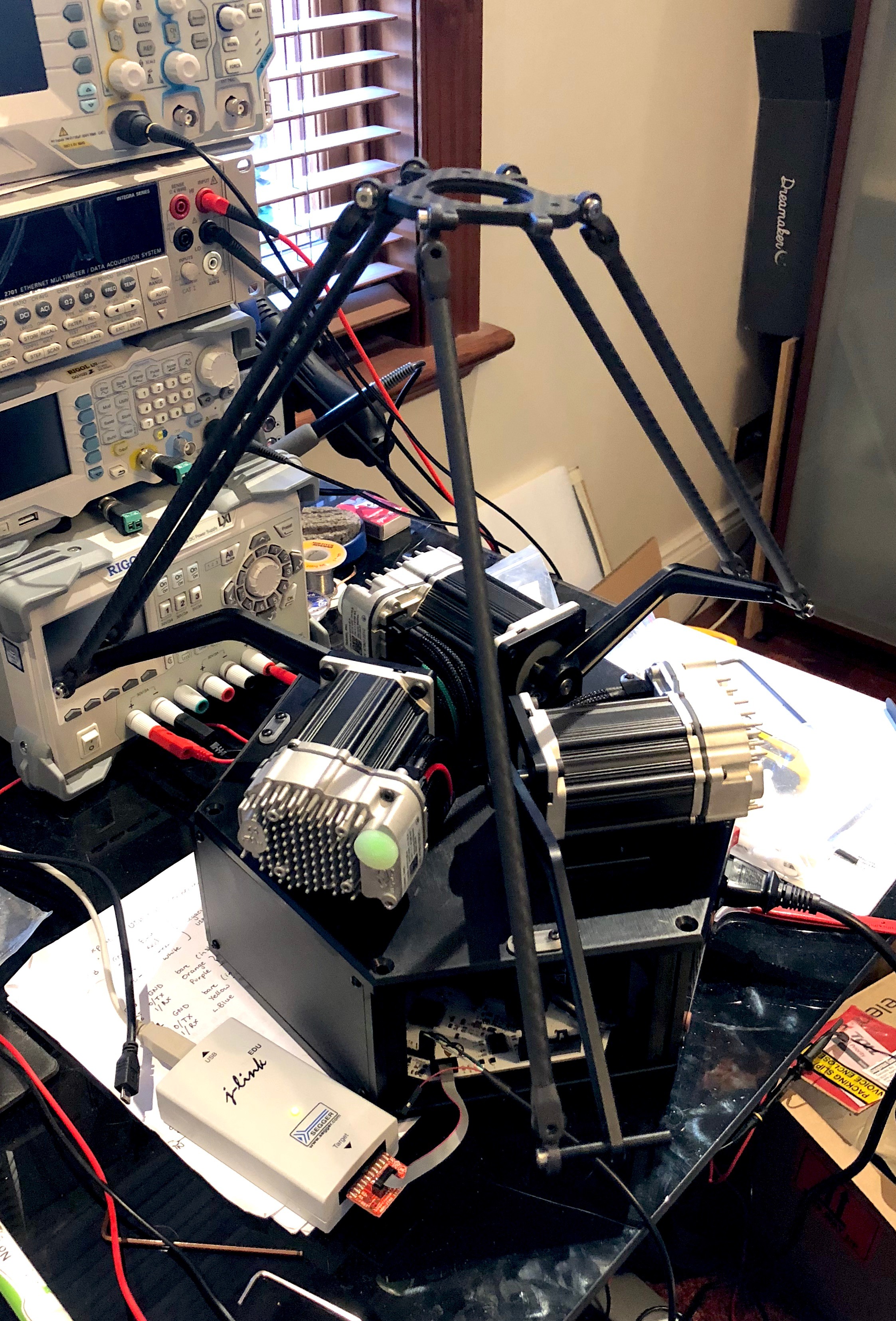
The photo shows the first time the servos were all enabled with functioning kinematics solutions. It was missing an arm and some parts of the linkages for some reason, but it was working!
After some cleanup and tuning, rough tests showed a maximum practical movement capability of 2meters/second and 3D positioning repeatability was validated to within 0.09mm with a dial indicator.
Realistically, these speeds weren't going to be achievable due to flex in the arm assembly, and its a bit too fast to be safe...
What's next?
For reference, this project is on Github.
While there are areas I should have gotten right in the first version, such as wiring management, 2-3 PCB tweaks to ease debugging, and some minor software refactor, it all worked fairly well!
The arm effector linkages were redesigned to use bearing pins rather than shoulder bolts, and the parts were sourced from Misumi rather than random Aliexpress vendors. These changes dramatically improved the consistency of joints, and reduced rotational play in the effector.
I covered the geometry creation and path planning process and preliminary results in another blog post.