Hardware CI Arena
Scott
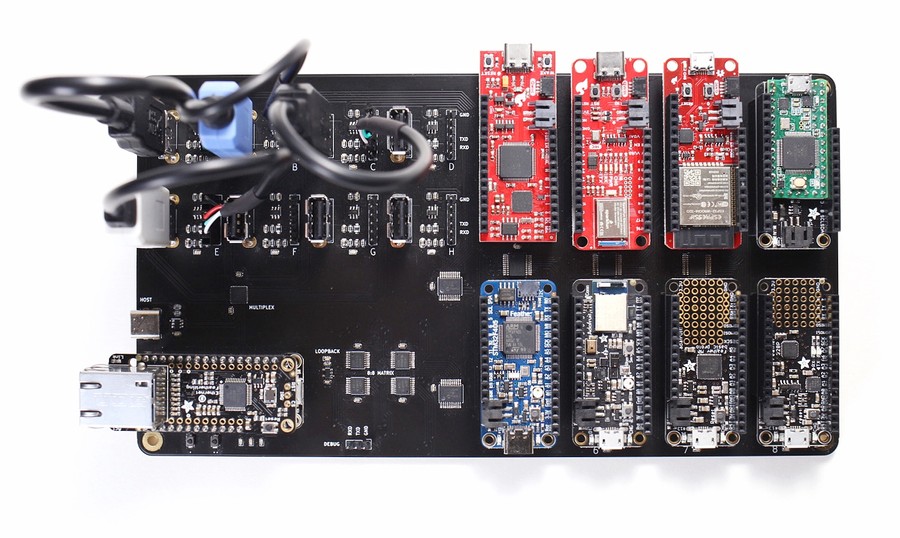
We develop Electric UI with standardised hardware targets to iterate quickly with common ‘known good’ hardware. During testing on some internal projects, we would occasionally discover differences in device discovery behaviour, connection reliability, and even found a few minor bugs.
Some of these issues were low level, or a result of cross platform differences, but we found some edge cases where USB-Serial adapters behave differently, and the default Arduino bootloader and 16u2 adapter on some AVR boards have some really annoying ‘features’.
We were already continuously testing our embedded library on a Arduino UNO and ATSAMD21 target against a Linux host, but decided to substantially increase our Hardware-in-the-Loop (HitL) tests to build confidence across most common configurations.
Aims
- Test a range of common USB to UART adapters,
- Test the most common microcontroller targets.
- Test the interaction of hardware against our UI on Windows, macOS and Linux OSes.
- Where possible, test hardware/firmware matches real-world settings (manufacturer configurable FTDI options, etc).
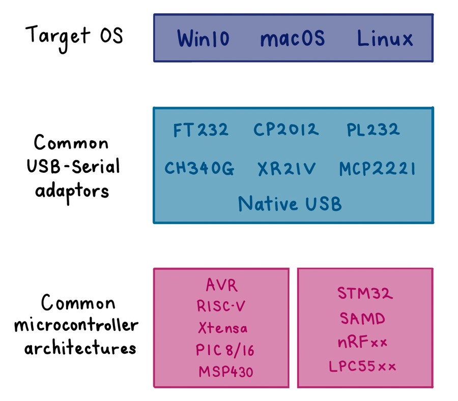
When we fleshed these requirements out with a list of adapters and microcontroller architectures (and the number of HAL/RTOS choices per target), the resulting matrix of tests started to look a bit daunting to just hang off the back of the build server...
Enter the Arena
Designed as a way of consolidating the mess of targets hanging off the back of the build server, a custom board opens up the ability to solve a few additional problems:
- Ability to test USB hot plug support,
- Perform low-level tests against specific USB-Serial hardware in loop-back mode,
- Test situations where the UART connection to the microcontroller is broken, or the target is power cycled independently of the USB adapter,
- Dynamic validation of hardware interaction with stimulus and response IO connected to each target.
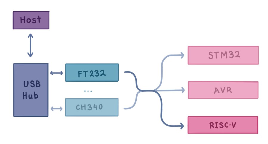
The conceptual design is straightforward: provide a USB hub or multiplexer for USB targets, controllable power switches on each adapter and target, and a serial routing matrix to connect adapter serial connections to any of our targets.
Designing the PCB
My first thought was to integrate all of the hardware on a single compact PCB and embed it in the server as a PCI card. In the end I decided that supporting off the shelf adapters and target hardware would make it easier to replicate other people’s setups while future-proofing the test fixture.
This meant using pluggable USB adapters and some kind of modular connection to the hardware targets. Due to the increasing popularity of the Adafruit Feather form-factor, I was able to find a good mix of hardware devices in electrically compatible boards.
Instead of a USB hub, I opted to use the simpler MAX4999 8:1 USB 2.0 multiplex IC.
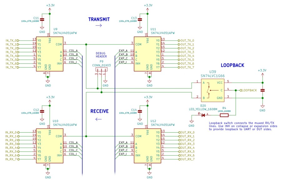
The UART routing is also really simple, with a pair of SN74LV4051A 8:1 analog multiplexers which demultiplex the 8 UART lines into one line, which is multiplexed out to the 8 hardware targets.
The multiplexers, power switches, and target microcontroller IO stimulus require a supervisory microcontroller which can be controlled by the CI/CD instance. To quickly achieve this, a Feather compatible micro with an Ethernet ‘FeatherWing’ was chosen.
As the Feather standard doesn’t expose lots of IO, MCP23008 I2C GPIO expanders were used extensively. This had the secondary benefit of easier board layout as expanders fan-out IO closer to the destination.
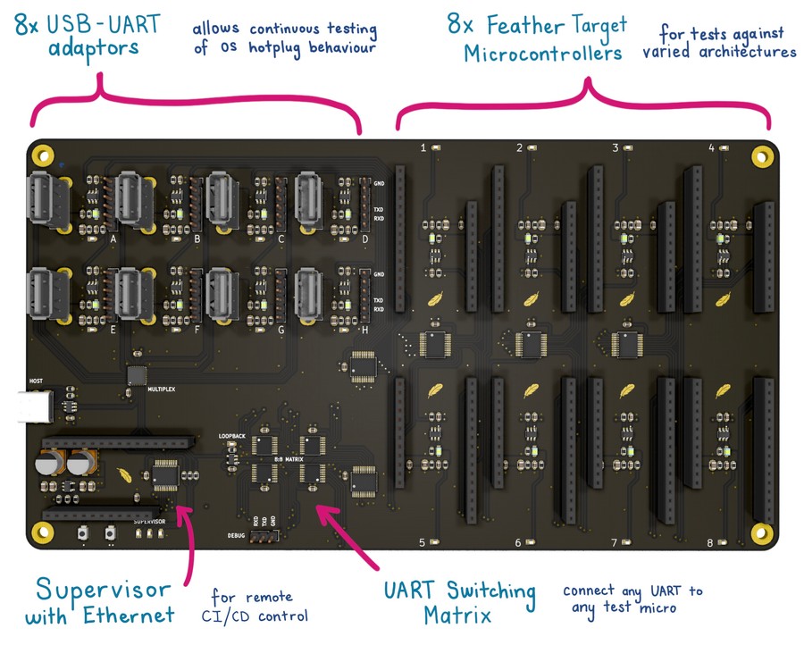
The board was designed in KiCAD, manufactured by JLPCB’s 4-layer JLC7628 controlled impedance process.
Assembly & Bringup
After parts arrived from DigiKey, a board was hand assembled with the standard paste + hot air.
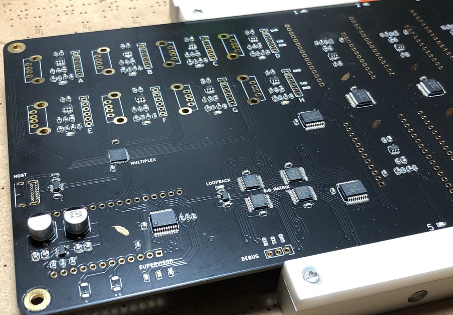
Because of the low unique part count and simple packages, assembly was uneventful and I could move on to validating the hardware.
I quickly wrote an Arduino sketch containing a MCP23008 driver, abstracted IO and mux settings, and some helper functions.
Ideally I’d check the eye-diagram for each of the USB ports, but my personal scope doesn’t support persistence particularly well. I ended up testing the USB routing by doing file copies to a USB flash-drive on each port and averaged 450Mbit/s with no issues. So far I've had no reason to doubt the reliability of the Arena hardware.
Firmware
After an uneventful bringup, I started adding Ethernet control capabilities. To make interaction simple in bash scripts or language specific test frameworks, the board just accepts HTTP GET requests for status information, and POST requests set the USB adapter, target, loop-back switch etc.
As a QoL feature, the board stores human-readable names for the USB adapters and microcontroller targets, allowing the test software to request specific hardware instead of specific ports on the arena board. These names can be queries and configured with some additional GET requests.
Example: Getting the human-friendly name of adaptor B
curl arena.local/adapter?b, returnsCP2012.
Example: Selecting the active microcontroller
curl -X POST http://arena.local/target -d stm32will power up and configure the serial routing for Feather 5.
Testing Hardware
Several of the targets share the same architecture (32-bit ARM), but the key distinction is the implementation due to vendor specific toolchains, the vendor HAL, use of an RTOS, the RTOS BSP, and also underlying peripheral implementations.
I proceeded to setup development environments for the test targets with a simple UART integration and GPIO interaction, and integrated electricui-embedded. The firmware column of the table links to example projects with the listed platform, but we use an internal testing variant to test as much of our API and protocol as possible.
| Arch | Microcontroller | Devkit | Firmware | |
|---|---|---|---|---|
| RISC-V | FE310-G002 | Sparkfun RED-V Thing Plus | Zephyr RTOS | |
| Xtensa | ESP32-WROOM-32D | Adafruit ESP32 Feather | FreeRTOS | esp32-uart |
| ARM M4F | Apollo3 Blue | Sparkfun Artemis Thing Plus | AmbiqSuiteSDK | - |
| ARM M4F | nRF52840 | Adafruit Feather nRF52840 Sense | nRF5 SDK | - |
| ARM M4F | STM32F405 | Adafruit STM32F405 Express | STCube LL | stm32-dma-uart |
| ARM M4 | K20DX256 | Teensy 3.2 | Arduino | hello-blink |
| ARM M0+ | SAMD21 | Adafruit Feather M0 Basic | - | - |
| megaAVR | ATMEGA328P | Adafruit Feather 328P | - | - |
These targets were used because Adafruit and Sparkfun stocked Feather compatible boards. I might design Feather compatible boards to add MSP430, PIC16/32, or RL78 targets in the future.
Testing Software
One of these Arena boards is connected to each developer's computer most of the time, with additional hardware inevitably hanging off our stacked USB hubs. The startup procedure of the Arena identifies this superfluous hardware and pre-calculates the hints that correspond to the correct hardware through correct routes. This avoids accidentally running tests on, or even communicating with hardware that isn't part of the test case.
Generating this information is inherantly stateful, and in addition to the variable timing involved with searching for hardware, integration with our usual testing framework (jest) proved difficult. Tests can't be run in parallel given everything must go through the Arena. Isolation of each test case into its own VM is a hinderance in this case instead of a feature - routing information shouldn't have to be recalculated for every test.
The reporting was also inadequate, giving us line numbers for errors that weren't exactly helpful in diagnosing communication problems. While most of the above problems have workarounds, it was clear that a code testing framework wasn't a good fit for a hardware-in-the-loop testing problem.
Reporting was the main feature consideration. Getting live data with progress bars for approaching timeouts, and detailed, helpful logs in failure cases was desired.
The Yarn Berry package manager boasts an excellent reporting system that was a heavy inspiration for our reporting solution. Notable features included the ability to write out logs that were 'not that important' until an error came along. In the happy path, they reach a maximum line length before 'rolling over', then collapsing down if the entire task completes successfully. In the error path, once the error is thrown all the breadcrumbs are left leading up to the problem.
These features were lifted from Yarn, in addition to niceties such as being able to supply a CancellationToken to a progress bar which would 'count down' to its deadline, giving a nice visual indication for tasks that relied on waiting for hardware / the OS to respond.
The test harness is simple. The matrix is configured through the HTTP API:
export async function setAdapter(adapter: string) { return retry(async () => { const response = await fetch(`${uri}/adapter`, { method: 'POST', body: adapter, }) return response.text() })}export async function setTarget(target: string) { return retry(async () => { const response = await fetch(`${uri}/target`, { method: 'POST', body: target, }) return response.text() })}export async function configureMatrix(adapter: string, target: string) { await setAdapter(adapter) await setTarget(target)}Handy helpers like retry let a promise returning function be specified that will retry with exponential backoff to smooth over any network / hardware difficulties that don't deserve a failure for the entire test case.
A matrix is built from the adapters and micros we want to test. For each combination, the device is found, then various tasks are completed in sequence to validate behaviour.
Below is the (simplified) test case for a handshake.
for (const adapter of ['ft232', 'cp2012', 'nativeusb']) { for (const micro of ['esp32', 'stm32', 'teensy', 'avr']) { report.reportInfo( MessageName.ARENA_CONFIG, `Configuring matrix for ${adapter}->${target}`, ) // Configure the matrix await configureMatrix(adapter, target) // Validate we can see the device const device = await findDevice(deviceManager, 8_000, report) report.reportSuccess( MessageName.UNNAMED, `Found ${device.getDeviceID()} over ${adapter}->${target}`, ) // Attempt connection await report.startTimerPromise( `Connecting to device...`, { wipeForgettableOnComplete: true, singleLineOnComplete: `Connected to device`, }, async () => { await device.addUsageRequest( USAGE_REQUEST, new CancellationToken().deadline(1000), ) }, ) // Attempt handshake await report.startTimerPromise( `Handshaking with device`, { wipeForgettableOnComplete: true, singleLineOnComplete: `Handshaked with device`, }, async () => { const progressReporter = Report.progressViaCounter(100) const streamProgress = report.reportProgress(progressReporter) // Handshake progress is converted to a progress bar const progressCallback = ( device: Device, handshakeID: string, progress: Progress, ) => { progressReporter.set(progress.complete) progressReporter.setMax(progress.total) progressReporter.setTitle(progress.currentTask) } // Listen to handshake progress events device.on(DEVICE_EVENTS.HANDSHAKE_PROGRESS, progressCallback) // Wait for the handshake await device.handshake(new CancellationToken().deadline(1_000)) // Cleanup listener streamProgress.stop() device.removeListener( DEVICE_EVENTS.HANDSHAKE_PROGRESS, progressCallback, ) }, ) }}Below is a recording of actual output from a selection of tests on a couple micros. Note how faster heartbeat rates result in faster validation of disconnection behaviour (as expected).
Results
With the hardware running, we were able to build out our test suite to include:
- Hotplug detection testing,
- Validation of the underlying serial connections, including the full range of possible configurations (start/stop bits, parity, baud rate),
- Handling of link disconnection during operation, and subsequent re-connection,
- Hardware tests against different architectures,
- Automated benchmarks to identify performance regressions
Ultimately, this fixture helps build trust in the behaviour of our reference communications library on a range of different targets, and validates the UI handshaking and connections code-paths.
By walking the potential connection configuration options we were able to find some rough edges which intersected with the Arduino bootloader behaviour, as well as proving some reliability issues with the PL232 chipset on my development machine.