Benchmarking latency across common wireless links for microcontrollers
Scott
I was recently trying to quantify the tradeoffs in user-experience for a wireless product and successfully nerd-sniped myself into evaluating a super-set of wireless modules and protocols.
While standards groups, radio chipset vendors, and IOT system integrators happily talk about improvements to bandwidth, long-range capabilities, or how low their power consumption is, I've really struggled to find substantive information about latency beyond hand-wavy marketing superlatives.
Calculating symbol rate and latency figures from radio first-principles is doable, but modern radio chipsets are also subject to protocol specific behaviours and increasingly complex software stacks. So let's experimentally compare them in 'typical' implementations!
Microbenchmarking embedded hardware
With any real-world project there are dozens of hardware and firmware design choices and optimisations that could meaningfully impact performance, and the matrix of potential tests becomes rather unapproachable if we also test across environments representative of real-world interference conditions.
While hardcore optimisation of each implementation isn't the primary focus here, I do want any comparisons to be fairly representative to the technologies and teams of engineers who've built them.
So I need to simplify this first round of testing by:
- Picking a smaller set of popular hardware options and protocols,
- Only performing 'bench tests' in a semi-controlled environment,
- Trying to answer one specific question: "How responsive can one-way wireless user interaction be?"
Some of the most common examples of this behaviour also happen to be the most latency sensitive: toggling lightbulbs, real-time review of sensor streams, and wireless control of actuators or robots.
Now that we know what we're testing for, let's work out how to measure the results.
Sizing Test Packets
Different use-cases may prioritise data rate or power consumption over responsiveness - a tank-level sensor has relaxed bandwidth and latency requirements, while a quadcopter control signal needs to be delivered with consistent latency and at a high rate.
Every communication link has a different set of design goals, but I want the tests to allow those design choices to be shown if possible. In my experiences with embedded systems, typical applications could describe their transfers with these common groups:
- Small packets with one or two small pieces of data, like a sensor reading or heart-beat value,
- Longer structures of data, many sensor fields, a set of configuration values,
- 'Big' packets containing chunked historical data, audio or images, and user-facing file transfers
So I'll test three different payload lengths: 12B, 128B, and 1024B, which should help shape a reasonable picture of how these wireless links behave. Some of the protocols have a MTU (Maximum Transmission Unit) which might not fit the larger packets, so where needed I'll break them into several packets.
Timing Capture
To keep things manageable later on, I'll be triggering each implementation with the rising edge of a logic-level signal (with a high priority interrupt) to trigger a new packet to be sent.
The receiving end will indicate a valid packet has arrived by driving an IO pin high.

There are a few reasons for this:
- Support for external trace probes, debug peripherals, and internal timekeeping quality varies between device,
- External test equipment can measure timing information for all targets equally in the lab,
- Testing latency and jitter over longer distances and in real-world crowded RF environments will be difficult using lab gear!
- Externally synchronised trigger pulses offer some semblance of consistency (GPS PPS, PTP?)
I'll capture the timing information with a Saleae Logic analyser sampling at 100 Msamples/sec (10 ns), and then post-process exported edge timestamps with a simple R script.
Test Validation
I'm fully aware of the complexities that come with remote communications in an embedded project, and that development time is better spent testing and optimising for power consumption or connection reliability. I expect the timing behaviour of most links' physical layers and respective protocols to trivialise any test fixture overheads, but I still want to quantify and eliminate benchmark artifacts.
Skimming the surface of possible optimisations sees us consider compiler optimisation settings, microcontroller clock tree configuration, peripheral use and configuration, use of an RTOS, and the weight of different hardware abstraction layers such as ST's LL (LowLayer), STM32Cube's HAL or the Arduino framework.
Without blowing this into a full dissertation detailing each hardware target, I'll try to demonstrate the impact of some of these choices using one of my preferred microcontroller families.
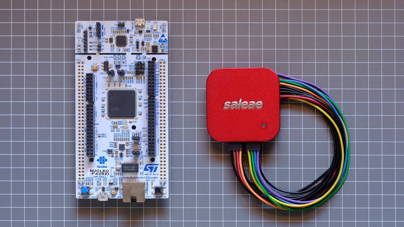
First, let's see how severe the impact of software choices might be on the results. Hardware is kept consistent across these tests - a STM32F429ZI micro is clocked at 168 MHz and running nearly identical code that catches the trigger signal via interrupt and drives an IO pin high.

While we expect release builds to be faster than debug and a bare-metal LL project to exhibit less overhead than an Arduino sketch, this 'quick example' still raises some interesting questions:
- Why does optimising for size (
-Os) run faster than optimising for performance (-O3)?- Due to different handling of a boolean check! Godbolt comparison here.
- For this contrived example,
-O1,-O2and-O3release builds give identical performance. - Over the next few tests with higher complexity,
-Oswas consistently slower.
- Why do the Arduino results have such a wide variance?
- Interestingly, the stm32duino project uses ST's LL internally, but deciphering where performance is lost needs its own discussion...
- As a simple answer, EXTI redirection and heavier peripheral housekeeping.
This generally matched my expectations. While I'll only show data using the LL and built with -O3 from here on, we should take a look at a more significant cause of test variations - hardware configuration.
Most modern micros support different strategies to manage performance critical peripherals: by polling registers, IRQ (Interrupt Request), or with DMA offload (Direct Memory Access). These configuration details are far more likely to impact latency, but it's important to point out that these choices are normally made to access specific features, reduce power consumption, or get out of the way of other application logic.
We need to communicate with some of our wireless modules using serial, so let's do a quick test of the UART peripheral using all three approaches and see why one of the best features of using DMA backed peripherals might not be so fantastic for these tests.

The majority of DMA tests have to wait for the UART peripheral to detect when the RX line is unused and generate an interrupt to wake the micro (usually one byte's worth of time, or ~87 µs). The small cluster of outliers nearly matching IRQ results is due to the DMA half-complete or complete interrupts firing when the final byte of the test sequence arrives.
This is normally less of a practical concern when handling other tasks or sending larger packets. The benefits for real projects are massively improved power consumption because the core can sleep for as long as possible without missing data, or other tasks can be executed with reduced overhead and context switches.
While the polling test appears to perform as well as IRQ, the micro needs to spend all of its time sending and checking for data. In real-world applications, it will miss data without careful cooperative sharing of CPU time with application workloads.
It's important to remember the context of these tests and the simple fact that implementation details are insignificant compared to increasing throughput - just waiting for 12 bytes at 115200 baud was responsible for 1041 µs of the 1050 µs, or ~99%.
| Baud | Bits/s | Bit duration | 8N1 byte duration |
|---|---|---|---|
| 115200 | 115200 bits/s | 8.681 µs | 86.806 µs |
| 230400 | 230400 bits/s | 4.340 µs | 43.403 µs |
| 921600 | 921600 bits/s | 1.085 µs | 10.851 µs |
So we actually want to look at the overhead, ideally as we increase baudrate to reduce the total transfer duration. This plot shows a range of tests where I've subtracted the theoretical duration for the 12 byte payload from the results.

When we ignore the DMA implementation's line-idle behaviour, the implementations have pretty similar overheads even as we increase the throughput by 16x. So it's probably reasonable to suggest that round-tripping (transmit and receive) data through my FIFO handling implementation results in an overhead under ~4.5 µs.
You didn't sign up for a lecture on embedded systems fundamentals, so I'll get into the actual tests now, but I don't want to contribute to the sea of subpar 'benchmark' blog posts without pointing out the importance of double-checking underlying implementation details.
Firmware, logic traces, R scripts, and raw/processed logs are in the git repo.
Radio Tests
Integrating wireless communications into any embedded project is ultimately an exercise in balancing compromises. The radio is often the most power hungry hardware for battery powered devices, and integration complexity and ecosystem interoperability generally drive the cost.
For 90% of use cases we start by considering the most forcing requirements:
-
Network topology
-
Pair of radios in a point-to-point configuration.
-
Two or more radios in a star or mesh network.
-
Single radio with end-user hardware, i.e. WiFi infrastructure, phones, etc.
-
-
Range (link budget) and throughput requirements
- 'Sub-gig' bands such as 433/868/915 MHz provide longer range but lower throughput.
- 2.4 GHz is shorter range, with far higher throughput.
- Differences in front-end filtering, transmit power, and receiver sensitivity.
- RF modulation schemes offer improved interference rejection to improve effective range.
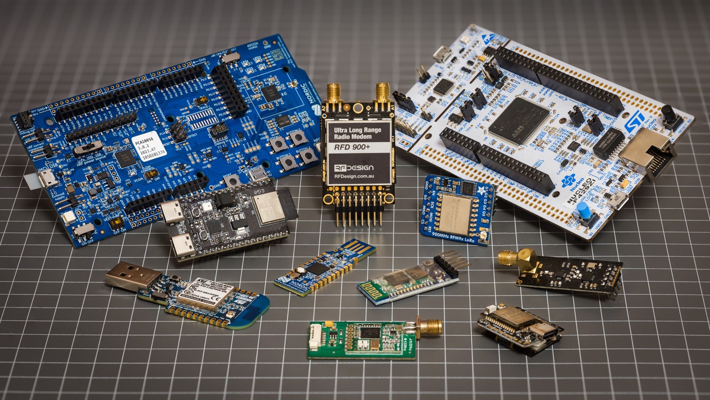
Selecting a small enough set of modules to cover all of these edges was hard. While I've tried to use the F429 Nucleo-144 with external radio modules, the most popular platforms for Bluetooth and WiFi are integrated microcontroller+radio parts. I've used the ESP32, ESP32-C6, and nRF52840 to help round out the test hardware.
SiK
Open-source modules based on the (now aging) SiliconLabs 10x0-GM RF+8051 micro running SiK firmware have been commonly used for the last decade as telemetry radios for long range UAV telemetry. In normal configurations they operate as a transparent serial link, though many have MAVLink aware firmware and support communications with multiple nodes.
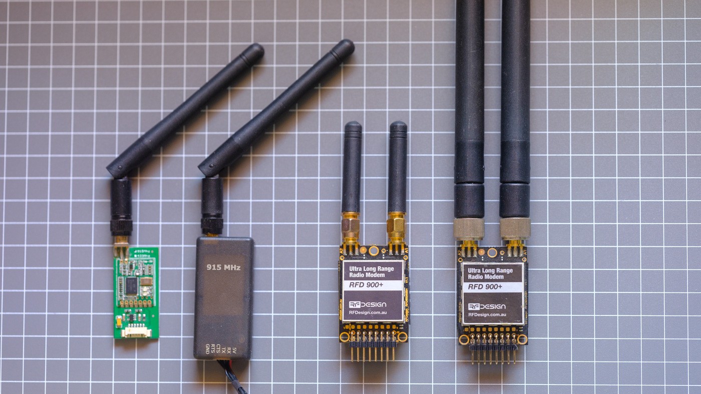
The smaller modules have been implemented and cloned dozens of times and use a minimal implementation normally rated for 100 mW output. The beefier RFD900 modules offer diversity antenna switching, better filters, and extra amplification (TX up to 1W).
These modules are tested with their default configuration - wired serial at 57600 baud, air data-rate at 64 kbit/s, and output power of 20 dBm (100 mW).

Hold on... on paper the process to send a 12 byte packet should naively take about 6 milliseconds (UART takes 12B at 57600 = 2 ms per side, 12B at 64kbit/sec = ~1.5 ms airtime) but we see a huge spread of latencies from a pretty reasonable 8 ms up to 130 ms.
Why isn't the magic transparent serial pipe just sending data when I do?

With some adaptors to connect an antenna to the spectrum analyser, we can peek into the transmission behaviour of the radio link to work out what's happening.
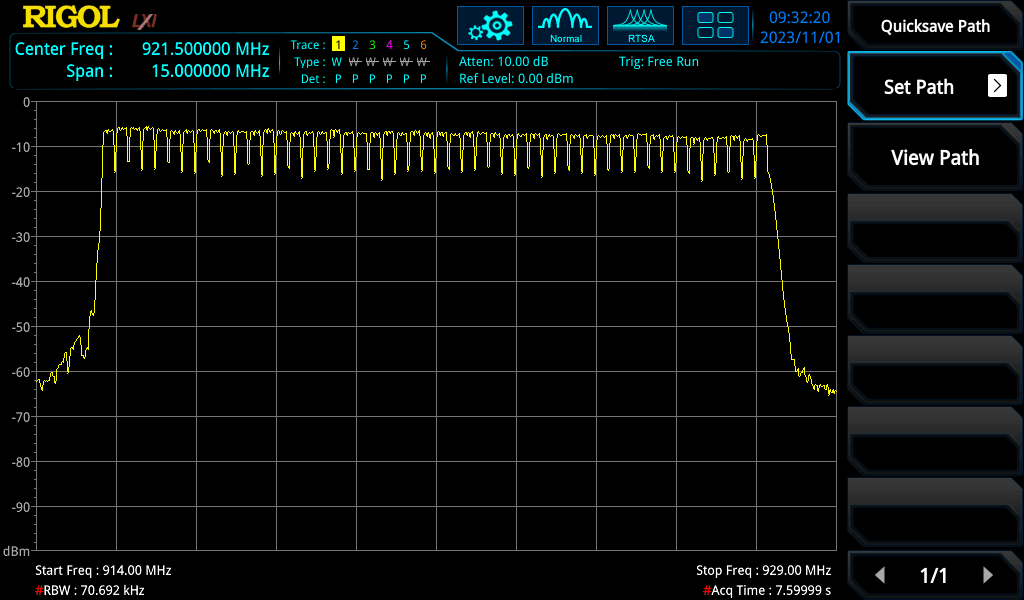
SiK radios use FHSS (Frequency Hopping Spread Spectrum) which rapidly changes the channel in a pseudorandom sequence. This spreads the signal over a wider bandwidth to help reduce interference and meet regulatory requirements.
By letting the analyser accumulate data for a little while, we can count out the 50 hopping channels across their configured 915-928 MHz frequency range. Nothing unexpected yet...
When looking at PvT (Power versus Time) plots, we can see distinct periodic transmit bursts from each of the radios with a lot of off-time. The 'receiving' radio module is an additional meter away from the spectrum analyser and has a slightly weaker signal in these screenshots.
By triggering on a power level threshold (shown as a blue horizontal line), we can get a more stable look at the radio while running the 12 byte test pattern.
What we're seeing is Time Domain Multiplexing (TDM) behaviour interacting with transmit behaviour, which can be grossly simplified into some simple steps:
- Synced modules hop to a new channel frequency at an agreed time,
- Each module is allocated a transmit window long enough for 3 packets,
- If nothing is in the buffer, send a zero length packet to yield to other radios (~2 ms).
- Up to ~232 bytes of buffered data is packetised with a preamble and header (~133 µs/byte). The 12B test payload should use ~3.7 ms of air time.
- If other radios aren't using their transmit time slots, continue sending packets if needed.
- When nothing else needs sending, listen in receive mode until the next hop!
Running the spectrum analyser's trigger output through a frequency counter tells us the modems hop frequency every 120 ms.
So the underlying radio behaviour is actually pretty close to our theoretical transmit duration, but the test conditions don't take into account that pending data is buffered by the module until the start of the next channel hop, leading to the wide variation in latency results we saw earlier.
This is also why the results are so evenly distributed - we're actually measuring the time we spend waiting for the next transmit window, and as long as the UART transfer arrives before the next window we don't gain any immediate benefit from a higher UART baudrate.
For a quick bit of fun, I tried using the RF power level (yellow trace) as a trigger input to the signal generator to synchronise the test IO stimulus signal (blue trace) with a configurable offset. With a 113 ms delay applied at the sig-gen, the microcontroller can reliably send it's packet just before an upcoming transmission window.
And we can now achieve a stable 9-15 ms latency result!

But that's not how these modules are configured or intended to be used, and the lab gear needed to achieve this timing hack is out of reach for most!
While the low latency result isn't indicative of real-world performance for these radios, I do think the process of exploring why is instructive and an indicator of what's possible for 'simple' point-to-point packet radios with a different design goal.
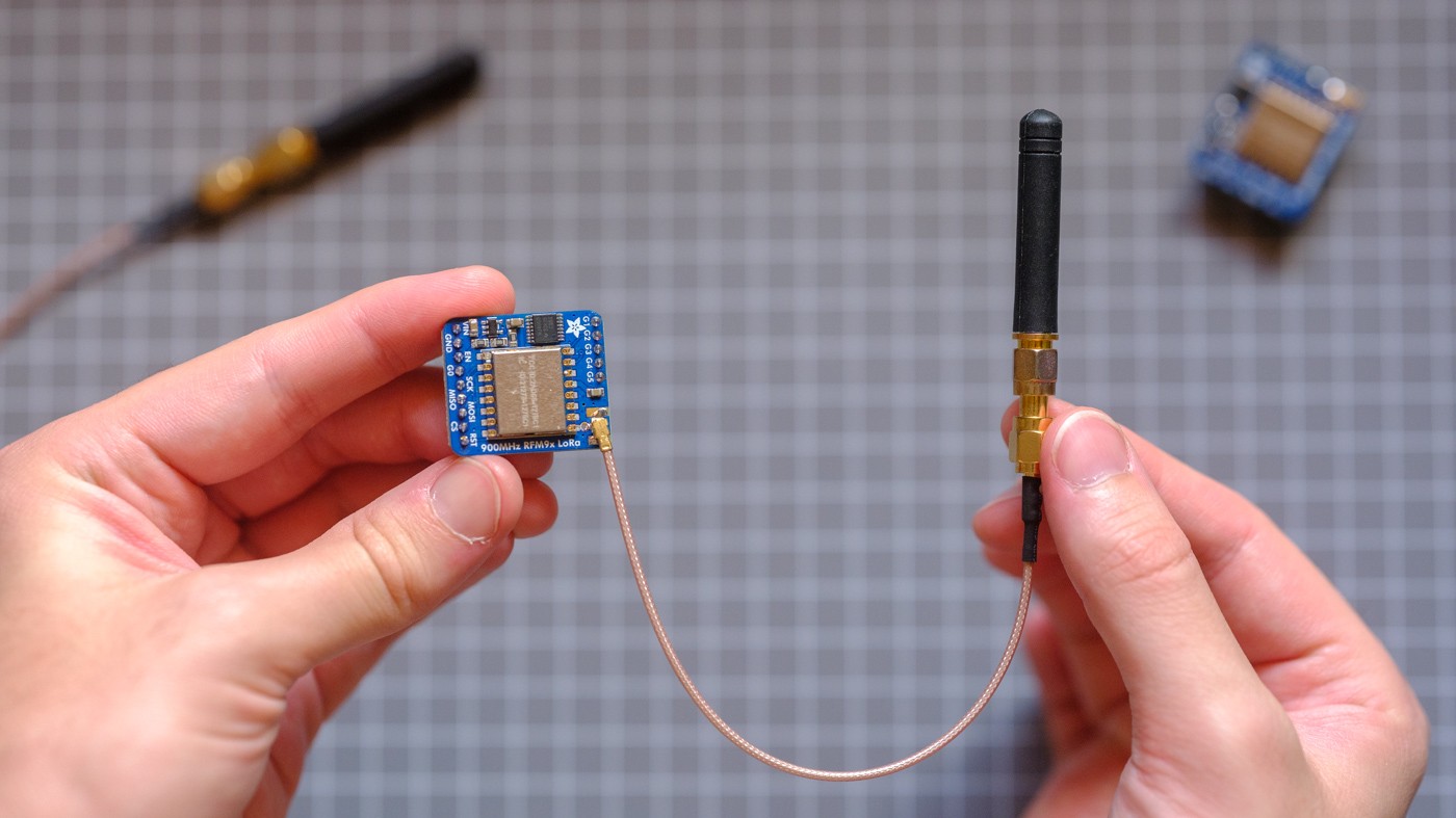
LoRa
In situations where periodic reporting of small messages from edge devices is needed, low power wide area networks (LPWAN) are an increasingly common choice for asset monitoring, smart power meters, and agri-sensing. The aim of these kinds of networks is to support large fleets of low-power nodes using one-hop star networks with an internet connected gateway.
LoRa (Long Range) is the brand name for the modulation scheme (physical layer), which uses CSS (Chirp Spread Spectrum) to achieve long distance communication with very low power consumption.
It's worth pointing out that LoRa has rather low data rates compared to the other radios I'm testing, maxing out at 37.5 kbps.
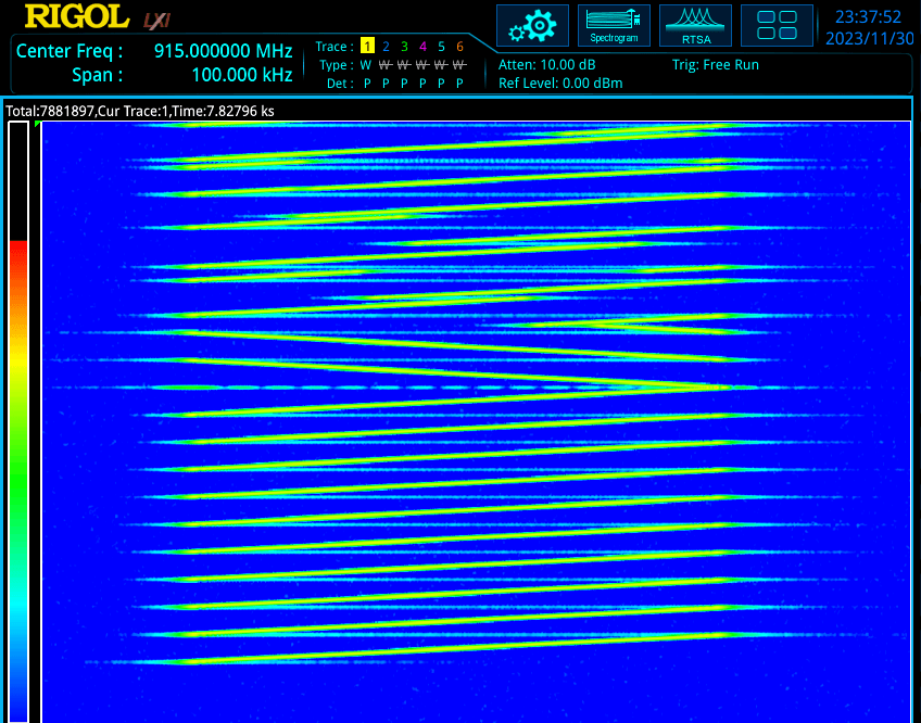
In the spectrum analyser waterfall below we can see part of a typical LoRa transmission. By reading from the bottom of the trace upwards, we see 8 preamble sweeps, followed by 2 reverse-direction sync message sweeps, then payload chirps continuing past the top of the waterfall. We can see the start and stop frequencies change for payload chirps, which is how LoRa transmits symbols.
LoRaWAN is the most popular of the higher level protocols (MAC) built on LoRa and has three classes describing when nodes can transmit, receive, or sleep. It also handles authentication, encryption, and message forwarding to upstream network services.
LoRaWAN uses a clever trick to improve capacity and reduce interference - by using different IQ (phase and quadrature) configurations for TX and RX modes, nodes can only hear transmissions from gateway radios and not other node transmissions.
The hardware under test is the Semtech SX1276 transceiver in the HopeRF RFM95W module (on an Adafruit Breakout board). The modules communicate with the STM32F429 using 10 MHz clocked SPI, and my LL based driver minimises timing overheads by using the transceiver's interrupt lines.
I'll test a point-to-point LoRa link, as I don't have an existing network or gateway on hand. If these tests were being performed with a real-world LoRaWAN I'd really be measuring any timing restrictions applied by the network - best practice is to normally sleep for minutes between packets to minimise air-time and power consumption.
I ran tests with two different chirp configurations representing sensible 'high speed' and long range use-cases. LoRa's maximum payload is 255 bytes, so the 1 kiB payload is broken into 5 transmissions.
| Bandwidth | Coding Rate | Spreading Factor | Data rate | |
|---|---|---|---|---|
| High Speed | 250 kHz | 4/5 (1.25x overhead) | 7 = 128 chips/symbol | 10.9 kbps |
| Long Range | 64.5 kHz | 4/6 (1.5x overhead) | 11 = 2048 chips/symbol | 224 bps |
Semtech's LoRa web calculator provides air-time durations which we can compare our results against. For the high speed configuration we can expect a 128 byte transmission to take ~107 ms.

Experimental results line up with the theoretical air-time timing, and the whole system has less than 10 µs of jitter (ignoring a dozen 128B outliers arriving 250 ms late) which is surprisingly well controlled.
As someone who predominantly works with micro-controllers, I'm most familiar thinking in milliseconds and microseconds, so seeing a calculated air-time of 5.4 seconds to transmit 128 bytes using the long range configuration hinted at a pretty scary 1 KiB transmit duration.

These are the longest transfer times of the hardware I tested, and I needed to increase the stimulus pulse interval up to 50 seconds for the 1 kiB tests - this meant I stopped capturing after ~100 samples (over an hour).
Benchmark results align with theoretical timings pretty well and are a good demonstration of the importance of minimising data transfer through careful payload design. These modules should better show their strengths in range and power measurement tests.
I'd love to know how many days deployed nodes have spent accumulating chunks of firmware updates...
nRF24
Nordic's nRF24 family of 2.4GHz transciever modules has been a commonly chosen option for custom wireless links for more than 15 years (early datasheets appear ~2006).
Over the years Nordic have co-packaged the transceiver with microcontrollers and USB interface hardware for tighter integration, and while they're not recommended for new designs I still see these part numbers appearing in regularly in research papers and hobby projects. The most widely known commercial use was in older Logitech wireless receivers.
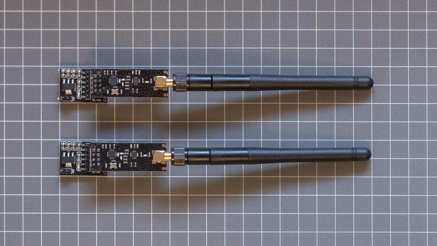
While it's hard to check if my 'genuine' modules are using cloned silicon or not, you can find barebones nRF24L01 modules using PCB antennas as cheap as $2 in single quantities on eBay (almost certainly clones) and fancier modules with low-noise amplifiers (LNA) and transmit amplifiers (PA) come with an external antenna for less than $10.
My interrupt driven implementation clocks the SPI link at 10 MHz (rated max) and configures the modules for maximum throughput with a 2 Mbps air rate. By enabling Nordic's Enhanced Shockburst the modules transparently handle automatic 16-bit checksums, acks, and re-transmit behaviour.
For the 128 and 1024 byte tests, the payload data is sent in chunks due to the nRF24's 32 byte payload limit. The next chunk is sent once the module's transmit success interrupt arrives. Enabling the dynamic payload length functionality impacted reliability, so any chunks requiring less than 32B are padded with 0x00 bytes (a 12B only packet test is shown below as Raw 12B).

Achieving a lower-bound latency of 300 microseconds for a 12 byte transfer is a great result and the tight clustering shows highly consistent behaviour.
The nRF24's low jitter is easily visualised with some RF PvT traces (shown in yellow). We can see the module starts it's first RF burst about 100 µs after the test stimulus trigger (horizontally offset by -2 ms) and the complete the sequence of bursts within 5 ms. The slightly lower amplitude bursts are the RX module acknowledging the transmissions.
By looking at the PvT behaviour with longer payload sizes, it seems like some of the variation is caused by occasional quiet periods between chunks. I haven't been able to work out why these happen.
I found it interesting that reducing the air-data rate to 256 kbps for 'long range' performance didn't impact latency as much as we'd expect from the ~8x reduction in rated throughput.

Long-range mode maintains highly consistent results but incurs a slightly less than 4x increase in transfer duration, less than half of what we would have expected from the air-data rate reduction.
| 256 kbps | 2 Mbps | Difference | |
|---|---|---|---|
| 12B (padded) | 1.5 ms | 0.4 ms | 3.75x |
| 128B | 7 ms | 1.9 ms | 3.6x |
| 1024B | 68 ms | 23 ms | 3x |
If I saturated the long-range link with more frequent test packets I suspect the difference would become more apparent.
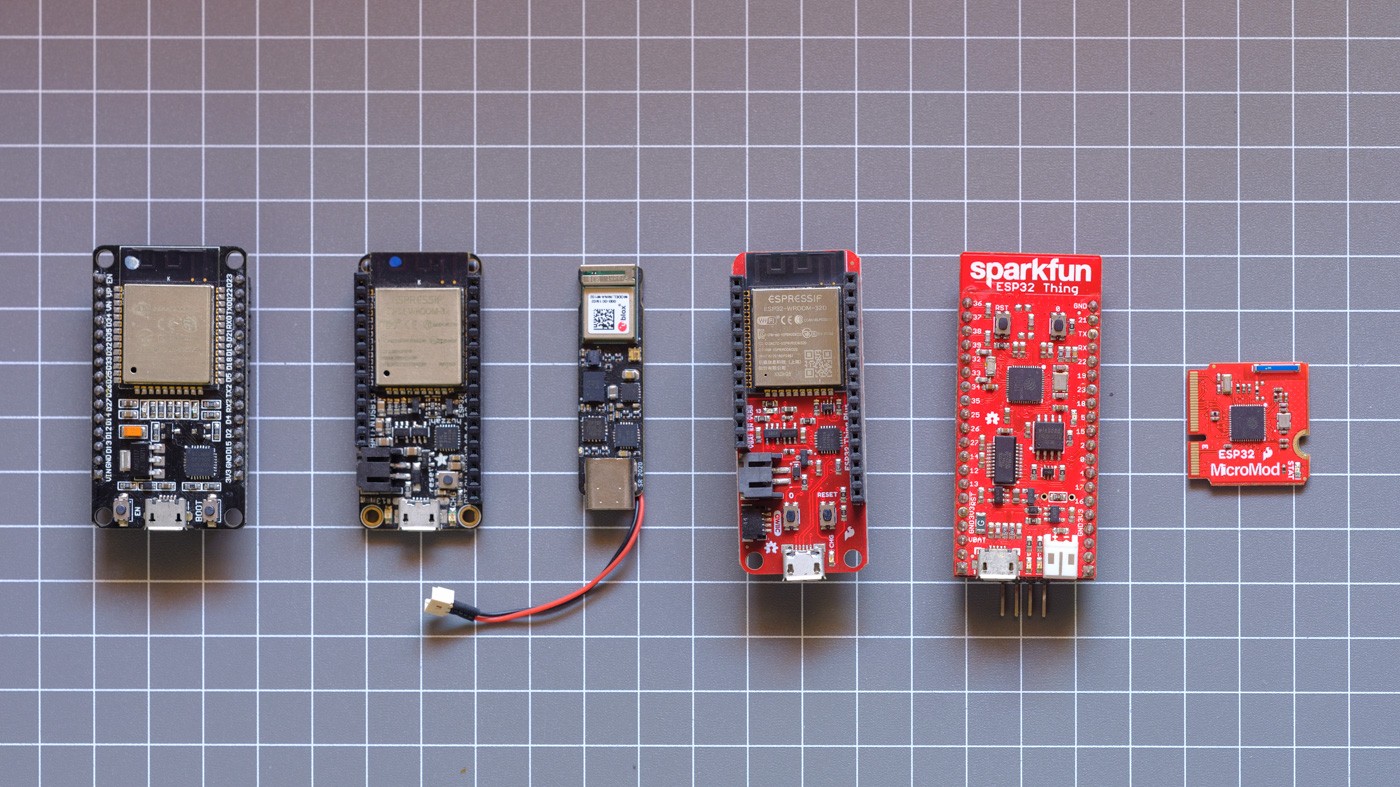
ESPNOW
The ESP32 and ESP8266 are probably the most popular hobby microcontrollers we've seen over the past 5 years, mostly due to incredibly low cost, integrated WiFi/BT, and pretty good development tooling from release. While the community has quickly grown fond of them, they're also found in a lot of commercial IOT products.
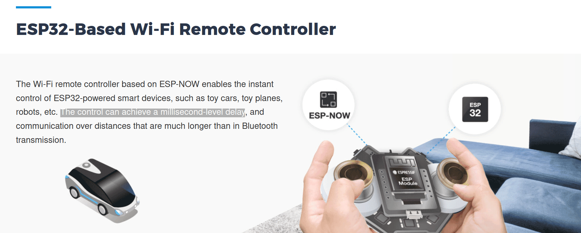
ESPNow is Espressif's proprietary point-to-point networking protocol running in the 2.4GHz band and is self-described as a low complexity option for smart lighting, sensors, and remote-control applications without a bridge or gateway. It uses a custom action-frame in the 802.11 Wi-Fi standard for specific device functionality which provides 250 bytes of usable payload space and typically runs at 1 Mbps.
The website does have a latency claim that it "can achieve a millisecond-level delay" which we can attempt to replicate.
Using Espressif's IDF example as reference, my stripped down implementation doesn't send complex structured payloads.
- At startup, the ESP32 boards find each other with some broadcast packets.
- If the broadcast came from a MAC address that hasn't been seen yet, add it to the peer list.
- If a trigger pulse interrupt occurs, search the peer list for our destination MAC address.
- Blindly send the test payload to that address as the only user payload information,
- Because the 1024B test exceeds the 250 byte limit, 5 packets need to be sent. I wait for transmit completion callbacks to succeed before sending the next chunk.
- The espnow task callbacks provide inbound packets which are passed to the main task loop with a FreeRTOS queue,
- Test packets are checked for valid length and checksum values using the same logic as earlier tests.
The results are pretty good - typical end-to-end latency for a single packet transfer is consistently ~5 ms. The 1 kiB payload shows good scaling behaviour as the 5 packet sequence takes ~24 ms to complete.

Interestingly, enabling long-range mode (which limits the PHY to 512Kbps or 256Kbps) hurts the 5-packet sequence slightly more than I'd expect.
802.15.4
IEEE 802.15.4 is a standardised physical and MAC layer protocol used most commonly for wireless home automation networks. Zigbee, Matter, and Thread are all high layer protocols built on IEEE 802.15.4.
Designed for embedded devices and low power consumption, it offers a reasonable range of data rates up to 250 kbit/second, three operating bands across 868/915/2450 MHz, and can operate point-to-point or with star network topologies.
I'm using a pair of Espressif's official ESP32-C6-MINI devboards for this test, which are 2.4 GHz only.
I opted to use the ESP-IDF's low-level ieee802154 library directly because it's small and very easy to work with (though building 802.15.4 MAC frames manually is tedious). There are also Zigbee and OpenThread example projects for these chips.
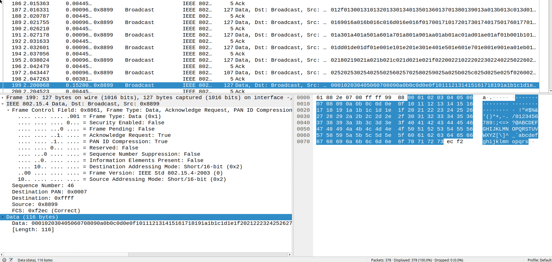
whsniff + Wireshark gives us a good view of the 9 chunks it takes to send a 1 KiB packet due to the 127B MTU.
I benchmarked both sending packets without acknowledgement aka "Blind", and with the acknowledgement request bit enabled.

The tight clustering of results is great to see, and a ~2.5 ms lower bound for small packets is fairly impressive. Generally speaking these are similar results to the comparable nRF24's 256 Kbps configuration.
Despite trying for a little while, I wasn't able to work out why acknowledged 128B test outperformed blind transmission. The difference isn't too meaningful, but if anyone reading knows why I'd love to hear from you.
Enabling the IDF Menuconfig's "Throughput Optimisation" setting didn't make any measurable impact for this test.
Bluetooth SPP
Often packaged alongside products as a 'wireless RS-232 dongle' or 'Bluetooth serial adaptor', modules implementing Bluetooth SPP (Serial Port Profile) act as transparent serial bridges and are the starting point for the dive into Bluetooth based transports.
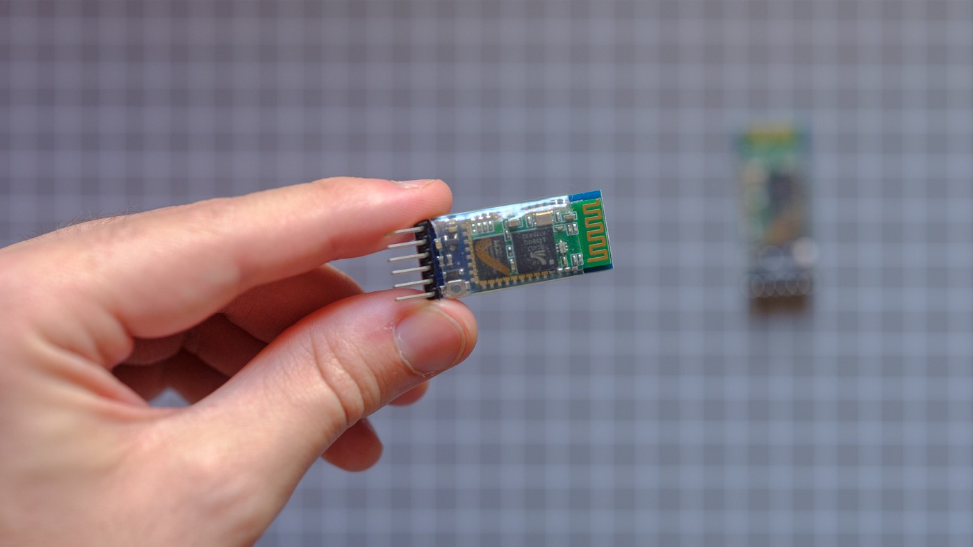
HC-05
The HC-05/HC-06 modules are one model commonly found embedded in hobby electronics projects as a zero-effort way to send UART data to a phone, PC, or between microcontrollers. These use Bluetooth 2.0 + EDR (now called Bluetooth Classic) and can allegedly reach air-rates of 1 Mbps at close range.
My modules arrived running 2.0-20100601 firmware and default to 9600 baud UART. I used AT commands to set one as 'master' to auto-bind to the second module.

The default configuration doesn't give great results, which is mostly caused by the low default UART speed.
At 9600 baud (8N1) it takes 1066 ms to transfer 1 kiB from the STM32 microcontroller to the HC-05 module. Increasing the baudrate immediately improves the situation.

Looking at logic analyser traces (diagrams simplified for readability), we measure a 20 ±4 ms overhead duration between the UART transfers for the 12B test. This behaviour is consistent with any UART configuration.

For the larger 128 and 1024 byte payloads the modules behave consistently at 9600 and 57600 baud. The receiving side starts emitting the payload before the full payload has been written out but the output is still one consistent stream.

460800 baud was the highest my modules would accept and still pass each of the payload tests. We still see the ~20 ms latency between sending the last byte and seeing it on the other side, but the stream now appears to arrive in variable length bursts. I've seen these bursts range from a single byte to 254 bytes, on a ~5 ±2 ms slot interval.

At these rates it's easy to overwhelm the modules by sending too much data - they handle this by dropping data randomly. This mostly justifies the slow default baudrate as it removes the need to consider rate limiting in userspace.
ESP32
We can compare the HC-05 behaviour against a pair of ESP32 modules as the Bluedroid stack supports Classic BT. We should also be able to reduce latency a little bit because the ESP32 doesn't need to incur micro-to-radio transfer overheads!
Similar to the other ESP32 test firmwares, my implementation follows Espressif's example but uses a FreeRTOS queue to pass write completion and inbound data events from SPP callbacks to a user task to handle the benchmark logic.
As the ESP32 in BT Classic mode has an MTU of 990 bytes, the 1 kiB payload requires splitting into two transfers.

ESP32 outperforms the HC-05 modules, achieving almost half the latency for smaller packets with the performance gap widening as payloads increase in size.
Espressif's docs reiterate some common sense - sending larger payloads less frequently is more efficient than high frequency smaller payloads. I experimented by forcing the 1 KiB payload into 32 and 64 byte chunks to compare against the 990 byte MTU result.

As expected, increased overheads mean smaller chunk sizes take longer, but we also see more variability in transfer timing.
Adding instrumentation and logging narrowed down the most likely cause as increased congestion events. Congestion flags bubble up from one of the lower levels of the Bluetooth stack (L2CAP) and signal that we shouldn't send more chunks until the flag is cleared.
Bluetooth LE
Introduced alongside Bluetooth 4 in late 2009, BLE (Bluetooth Low Energy) was designed ground-up for low power devices with the goal of improving compatibility with user devices like smartphones. Since then we've seen an explosion in app-connected products across pretty much all consumer markets and even industrial hardware, with the majority of these devices using BLE.
BLE devices communicate using the GATT (Generic ATTribute Profile) server-client model: the server describes data (characteristics) and metadata (attributes), and client devices (a user's phone) read or write against these characteristics. You'll often see them called Peripheral and Central in Bluetooth documentation.
The BLE specification restricts the minimum connection interval to 7.5 ms, so I'm expecting all of the implementations to achieve lower-bound results under 10 ms. The BLE Throughput Primer on Memfault's blog covers many of the underlying behaviours being exercised in this section.
ESP32 Bluedroid
The test firmware configures a pair of ESP32 boards using a typical approach for connecting a sensor node (peripheral/server) to an 'end user' style device (central/client). GATT servers have the ability to 'push' data to the client using either an Indication (requiring acknowledgement) or Notification (without acknowledgement).
I compared the latency of the server notification approach against the client's 'Write Without Response' by supporting both directions of data transfer in the implementation and simply swapping the test setup to trigger the client board.

I hadn't properly tested this specific detail before and didn't expect to see much difference in latency, but we have a ~5ms difference with some outlier client writes extending past 40ms. I'd be surprised if this detail would be a show-stopper for real-world projects though.
The Notification test data show some distinct distribution bands of higher density.
These groups are roughly 7 ms apart, which has a strong correlation to the minimum 7.5 ms connection interval for BLE.
Continuing with the different test payloads sent via Notification, both the 12B and 128B tests fit inside the ESP32's recommended 200 byte MTU, but the 1 kiB test needs 6 packets to send.

These results are fairly good, but it's hard to see an improvement over the older Classic SPP results from the ESP32 without considering the differences in power consumption and vastly better end-user connection experience.
ESP32 NimBLE
While the Bluedroid stack was used for the previous ESP32 BLE tests, the ESP-IDF also supports Apache's MyNewt NimBLE stack which has been developed specifically for low-power and memory constrained hardware.
I couldn't find any information about any potential performance or latency benefits, so I re-implemented the BLE SPP firmware to see how NimBLE stacks up.
It's worth pointing out that Espressif's NimBLE examples don't match their README. Also, be prepared to dig through scraps of MyNewt documentation to implement MTU exchange and subscriptions to achieve feature parity with the Bluedroid example.

Odd, that's not what I expected at all. Before we jump to any conclusions, let's test the other payload sizes with the same setup as the previous SPP and GATT tests...

There's clearly a few things wrong here, these NimBLE test results are meaningfully slower and far less consistent than the Bluedroid stack. I'm also rather confused by the inversion in latency for client writes.
I asked Espressif if everything was working properly, then went poking for a few days while waiting for a response.
At the time of publishing there's been no official response...
Things improved somewhat with manually specifying faster ble_gap_upd_params for interval and connection timings (fixing the 40 ms gap spacings), but it wasn't until @xyzzy42 dropped a hint in the issue thread a few weeks later which led to some additional configuration.
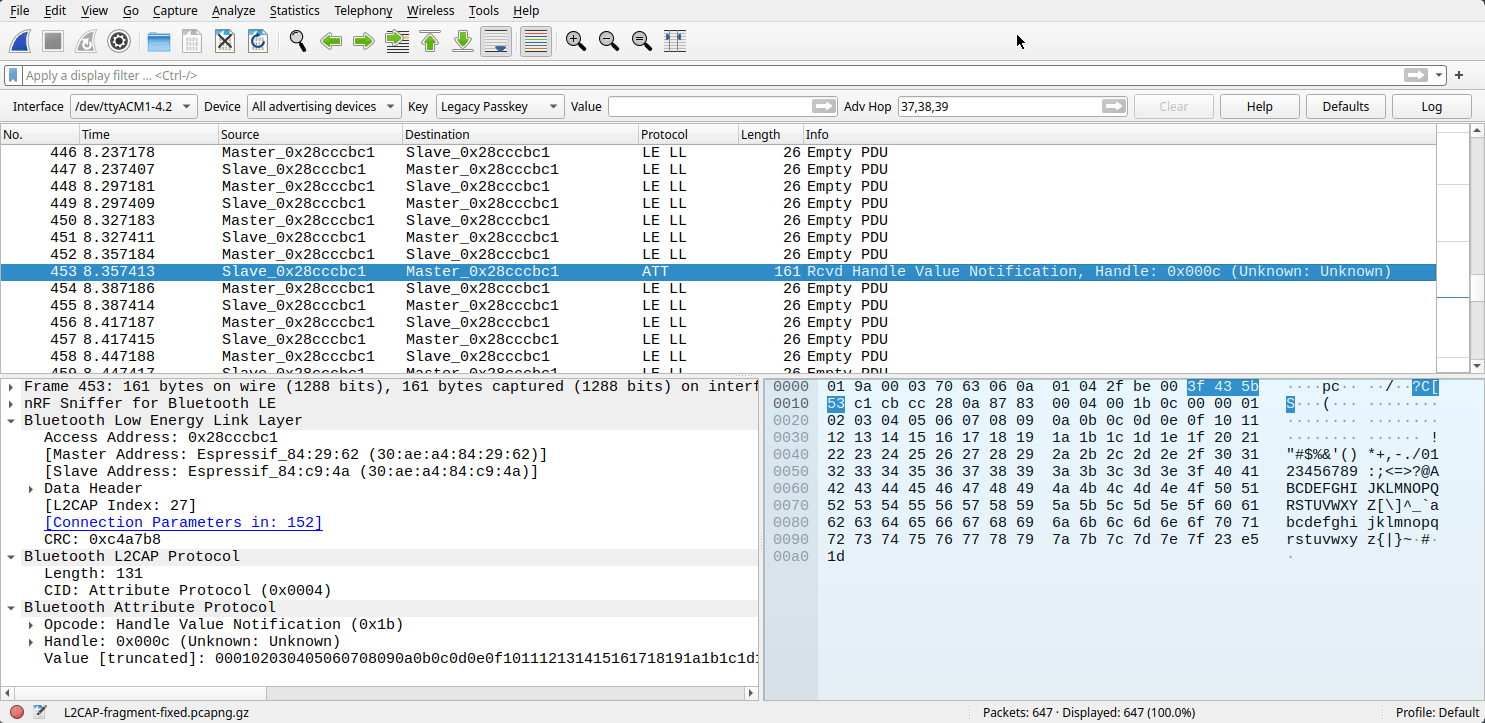
Looking at some sniffed BLE captures in Wireshark we can see that our packets are being broken into six 26B fragments even though the peer confirmed our larger requested 200B MTU value during connection.
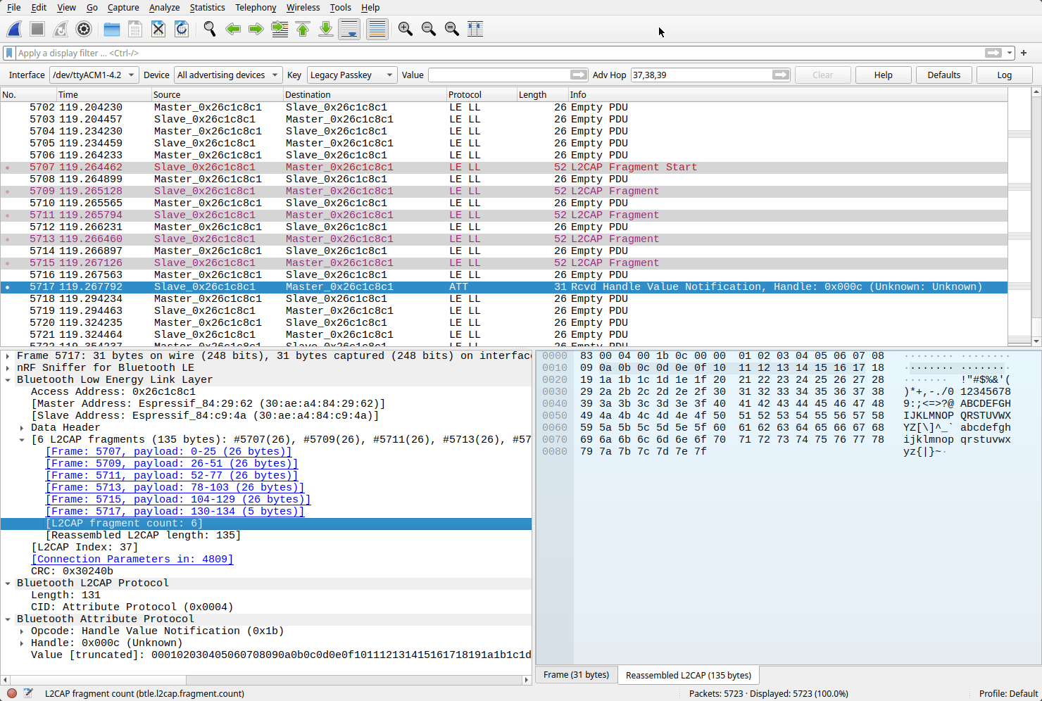
So the low-level controller's MTU doesn't seem to be affected and packets are being automatically fragmented and reassembled by L2CAP. Espressif uses an intermediate VHCI (Host-Controller Interface) layer between the NimBLE Host and the underlying Bluetooth controller, which is probably where this rough edge comes into play.
By calling the NimBLE's ble_gap_set_data_len(handle, tx_octets, tx_time), we're making a (wrapped) call against the ESP32's Bluetooth HCI which does make the configuration change we wanted. We can sniff the connection and see it behaving correctly in Wireshark.
Running the benchmarks again, we see that these changes have contributed to a massive improvement to variance, and both the best and worst-case latency results are halved for the 1024B test.

A generally better result and mostly matching Bluedroid's defaults. I haven't investigated power consumption or resource usage deeply (yet) but I'd still want to pick Bluedroid with the ESP32 based purely on the quality of examples and documentation.
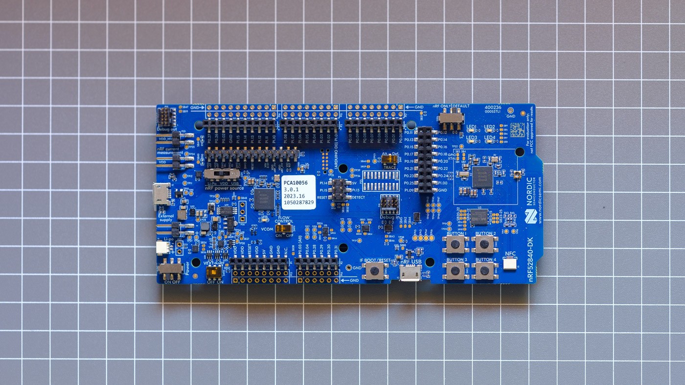
nRF52
Implementing the same BLE behaviour with a platform designed around Bluetooth is worthy of comparison. I bought a pair of Nordic's nRF52840-DK boards and implemented the benchmark tests using the "Nordic UART Bridge Service (NUS)" library which provides helper functions and vendor-standardisation for a GATT-based generic data transport.
The implementation is similar to the handful of ESP32 projects tested earlier, but Zephyr RTOS has some slight differences in approach and runs on a higher tick rate than FreeRTOS. Just like most of the other tests, I needed to spend some time experimenting with BLE configuration to get fair results as the defaults were a bit relaxed.
One notable difference to the other BLE implementations was consistent performance regardless of the transfer direction between boards.

Something I found interesting during early tests was impressively tight clustering of results (within ±1 ms) for shorter benchmark sequences. Over longer spans of many minutes the distribution of results ranged more evenly.
This was a clear demonstration of accidental alignment and subtle drift between the stimulus signal and the boards waiting for the next BLE transmission slot. As a result, I'm including a variation test run here to give a better impression of latency spread in less controlled environments:
- Normal periodic trigger pulse interval,
- 'Randomised' trigger intervals to mitigate synchronisation biases with the connection interval. The signal generator's sweep functionality slowly added +50 ms to the normal pulse interval.

The tight clumps of results are aligned to multiples of the connection interval. We can also see the expected behaviour that larger packets increase the widths of the clusters. Outliers aren't anywhere to be seen, and the lower-bound latency for the 1 kiB packet is half of the ESP32's best BLE result.
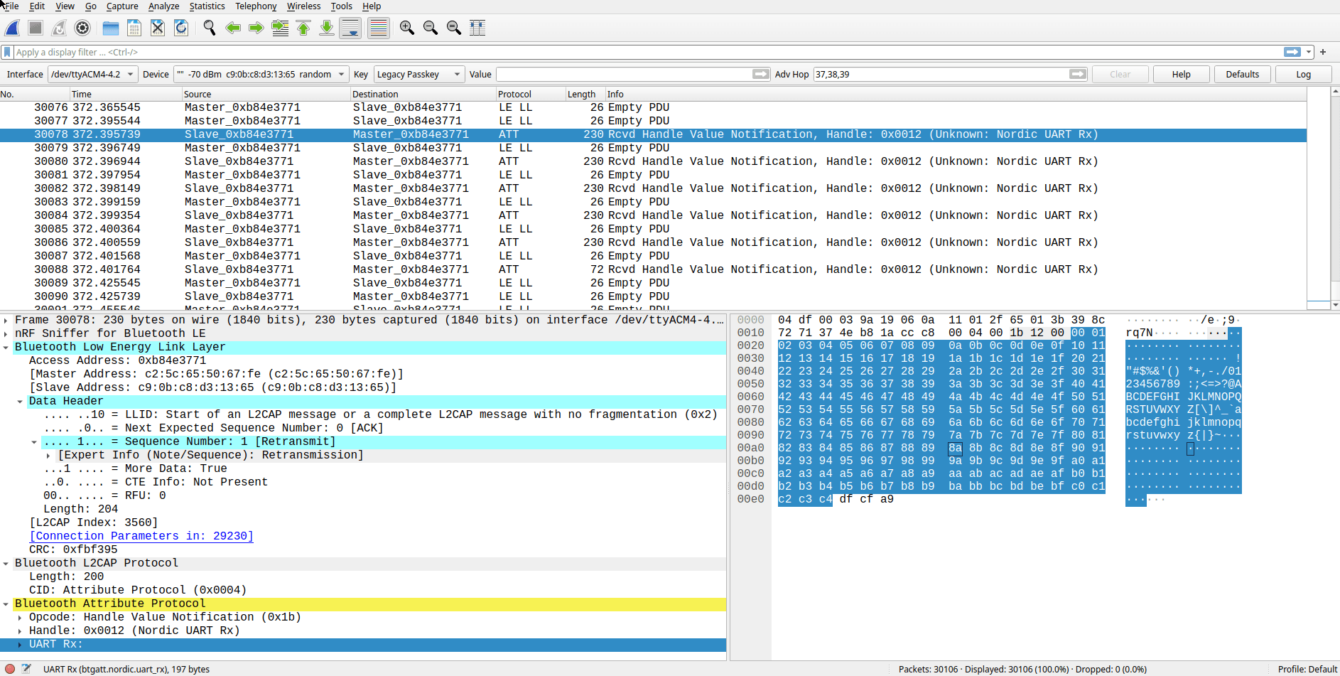
Sniffing a 1 KiB test with Wireshark shows us the idealised 1 KiB transfer sequence in action, 6 packets immediately after each other taking ~6 ms combined. So we're still really limited by the connection interval!
Nordic get brownie points for their documentation and examples working first try without modification, and the inclusion of GATT based Latency and Throughput APIs shows us what the bare minimum should be for developers to reasonably reproduce and test their hardware.
WiFi
Given the ESP32's core feature is its WiFi support, we really should see how it stacks up. Again, we're only looking at latency and ignoring the limited range and higher power consumption.
First up, non-blocking TCP and UDP socket implementations between the two boards using existing WiFi infrastructure (Unifi U6+ about 5 meters away, 8 other 2.4 GHz clients).
All of the test payloads can fit in a single packet and the boards are running at 72 Mbps PHY rate (HT20) which should trivialise test payload timings with sheer throughput.

Once again, we're seeing the ESP-IDF default configuration underperforming the expected latency results. For context, pinging either of the boards from my workstation gives ~7 ms results.
Going through the docs and forums shows us a few knobs we can turn - playing with the modem's power-saving modes, ensuring the WiFi and LwIP stacks are in IRAM, and disabling Nagle's Algorithm for TCP.

Much better. Both TCP and UDP were able to achieve the same lower-bound latencies and similar worst-case outliers. UDP is shown with a ~2.5 ms higher median which I attributed to the more even distribution of results in the span, but I'd consider it too-close to call for this micro-benchmark.
In real-world projects it's more common to see high-level protocols over raw sockets, especially given how often integrations need to support phones, web services, and 3rd party systems. WebSockets are a pretty popular choice and we'd expect them to perform similarly on the ESP32 to our TCP results.
Espressif's example projects (esp_websockets_client and ws_echo_server) provided a better starting point for the benchmark implementation than the LwIP socket implementations.
At this point I shouldn't have been surprised, but I really struggled to achieve consistent run-to-run results across many testing and optimisation attempts.

While drafting a highly detailed GitHub issue I worked out that I was being thwarted by Nagle's Algorithm again, needing a slightly different approach to disable it when using the httpd server library.
static esp_err_t ws_server_handler(httpd_req_t *req){ if (req->method == HTTP_GET) { ESP_LOGI(TAG, "WS Handshake Complete"); // Modify the underlying TCP socket. Surely there's a better way? int sock_id = httpd_req_to_sockfd(req); int no_delay = 1; setsockopt(sock_id, IPPROTO_TCP, TCP_NODELAY, &no_delay, sizeof(int)); return ESP_OK; } // Rest of websocket packet handling code
As expected, there's no meaningful impact of packet size due to the high link throughput, but we can see that Websockets have cost us around ~6 ms over the lower-level TCP socket implementation (this could be phrased as "double the latency" for clickbait?). Larger packets repeatedly tested faster than smaller transfers for some unknown reason.
So while WebSockets are a lot easier to work with, as implemented, they do have a latency cost on the ESP32.
For a quick comparison, a pair of Raspberry Pi's using onboard WiFi can achieve Websocket transfer results on-par with the ESP32's TCP results, with a pretty minimal NodeJS implementation.

The Pi's outliers are spread a little wider than I'd expect (especially when on Ethernet) but digging into network and performance tuning of Linux and run-times like Node isn't something I'll be doing in this post!
Results
We finally made it! It only took 10k lines of code, a new year, and running an overwhelming >200 tests across the different targets...
To make comparisons easier, we're going to start with a barchart of the upper quartile latency figures as I think they're most statistically fair across the board.

When I started these micro-benchmarks I didn't expect the nRF24 module to perform so well - it recorded the lowest minimum, lower/upper quartile, and median for 12B and 128B payloads.
We can see an interesting trend with the top three results: despite strong performance for the small and medium payloads, their 1 KiB results are alongside the BLE implementations in the midfield. The common element between them is the small MTU which requires many chunk transfers.
Unfortunately, the NRF52 is placed second-to-last in this chart due to it's 75% latency result being just slightly higher than the HC05 and LoRA 12B results, even though it's median should place it alongside the ESP32 BLE (Bluedroid) implementation.
The 915 Mhz LoRa and SiK modules come in last place as expected - low-throughput links optimised for long range are going to struggle in a test that favours high throughput. I expect these modules will fare better when I look into range and congested RF environments in future tests!
60fps is generally considered the lower-bound for playable game framerates, at just 16.6 ms per frame.
In general, most radios achieved average small-packet results lower than that!
Because so many of these tests used an ESP32, we should have enough data to compare the different protocols and wireless stacks when using the same RF front-end. Most protocols had similar performance with 12B and 128B packets - they all have a MTU exceeding the 128B test and used (relatively) high throughput links.
I've plotted the probability distribution for each protocol against latency. This lets us make more intuitive comparisons between protocols than another set of box-plots. Picking a point on a line tells us what percentage of a test's results had finished prior to that duration.

There are a few general findings that are fairly obvious:
- As packet size increases, WiFi's higher throughput beats everything.
- When using WiFi with TCP/IP transfers, there are only small differences between TCP, UDP and Websockets performance for these benchmark conditions.
- SPP leads over the BLE results, probably due to it's ~5x larger 990 byte MTU.
- If using BLE on the ESP32, the Bluedroid stack is lower latency than NimBLE.
Development Experience
The easiest implementation was the ESP32-C6 with IEEE 802.15.4, followed by the transparent UART bridges SiK and HC-05, and ESPNOW.
The most time consuming part was implementing and testing the RFM95 LoRA modules, as I burnt time trying a few different OSS libraries with design issues ranging from blocking sleeps, bugs, and polling the module's status IO instead of using interrupts.
However the most frustrating work was troubleshooting the NimBLE stack on the ESP32. The perfect storm of sub-par default performance, stale example projects, and needing to continually cross-reference between the Espressif and MyNewt documentation websites and source-code.
What wireless module is best for my project?
I see this question all the time online, and it's hard to advocate for a specific radio module or protocol over another based on latency alone.
One of the takeaways of these tests should be how capable modern radios are and when they have ability to use multiple protocols (often at the same time), this becomes more of a software choice than hardware!
For microcontrollers with integrated radios:
- Newer Espressif parts like the ESP32-C6 are a compelling choice for their low cost, reasonable tooling, community support and capable hardware which offers so many protocol options.
- I ran out of time to compare the older ESP32 against the newer C6 part, but it's newer WiFi 6 capable radio should offer better performance,
- I'll definitely be building with the C6 and 802.15.4 in future projects...
- If you can tolerate a steeper learning curve and have climbed a DeviceTree before, then Nordic's nRF parts offer a more consistent developer experience and first-party examples.
- ST's WB/WL series is worth looking at, but have caused me a lot of pain previously.
If you're adding an external radio to your microcontroller and don't need the best possible performance, any transparent UART bridge is a good low-effort choice.
The nRF24 performed well in these tests but is rather dated at this point. Probably still a reasonable choice for simple one-off projects, otherwise look at the nRF5's Shockburst support for more recent options.
Still not sure? Look for modules that use SPI to maximise performance. A good starting point might be looking at the RadioHead Arduino library which supports a wide range of modules.
Key Takeaways
The process of implementing and testing each of these modules reinforced a couple of valuable lessons:
- Fantastic low-latency communication links are more accessible than ever.
- Unsurprisingly the balance between power consumption, throughput, and latency matters - and default settings are often on the conservative side.
- If you need the lowest latency and tight control over your system's behaviour, you'll probably find the best results with a wireless stack that isn't trying to co-exist with other protocols or devices.
- Even when you're doing everything properly, validate with scope traces and Wireshark captures.
- Benchmarking things properly is really time consuming!
I'm thinking of doing a suite of real-world range tests against a sub-set of these devices, and would love feedback if you found this helpful or interesting (or have any corrections/suggestions).
References & Acknowledgements
Discussions on HackerNews, /r/embedded, and Hackaday.
- Henri Heimann's
stm32-hal-rfm95and PeeWeeLabs'spwl_rfm9Xas reference material. - Semtech's LoRa calculator, and Yung-Hsiang Hu's
lora-air-timecalculator as a sanity check. - Ilia Motornyi's
nrf24l01-lib. - Espressif's
ESP-IDFexample projects. - Martyn Currey's blog post detailing HC-05 AT Commands.
- BLE Throughput Primer on Memfault's Interrupt blog.
@xyzzy42for NimBLE configuration suggestions.- James Barwell's
rpi-gpioNodeJS library. - WaveDrom for
svgtiming diagrams. - R and RStudio.
- Cedric Scherer's blogpost on Raincloud plots.
- BoxPlotR (GitHub) for
svgboxplots (eventually replaced by my own script). - Paul Tol's Introduction to Colour Schemes