ElectricUI Binary Protocol
The default serial protocol for Electric UI provides a fast way to get started.
- Supports human readable message identifiers of up to 15 characters,
- Payload sizes up to 1kB per packet,
- Inbuilt support for splitting larger data structures over multiple packets,
- Included type information allows for zero-configuration,
- Features isolated namespaces for developer messages and internal packets,
- Supports acknowledgement numbers and query behaviour,
- Bandwidth overhead of 7-9 bytes per packet[^1]
- Checksum and frame encoding provide error detection and fast failure recovery.
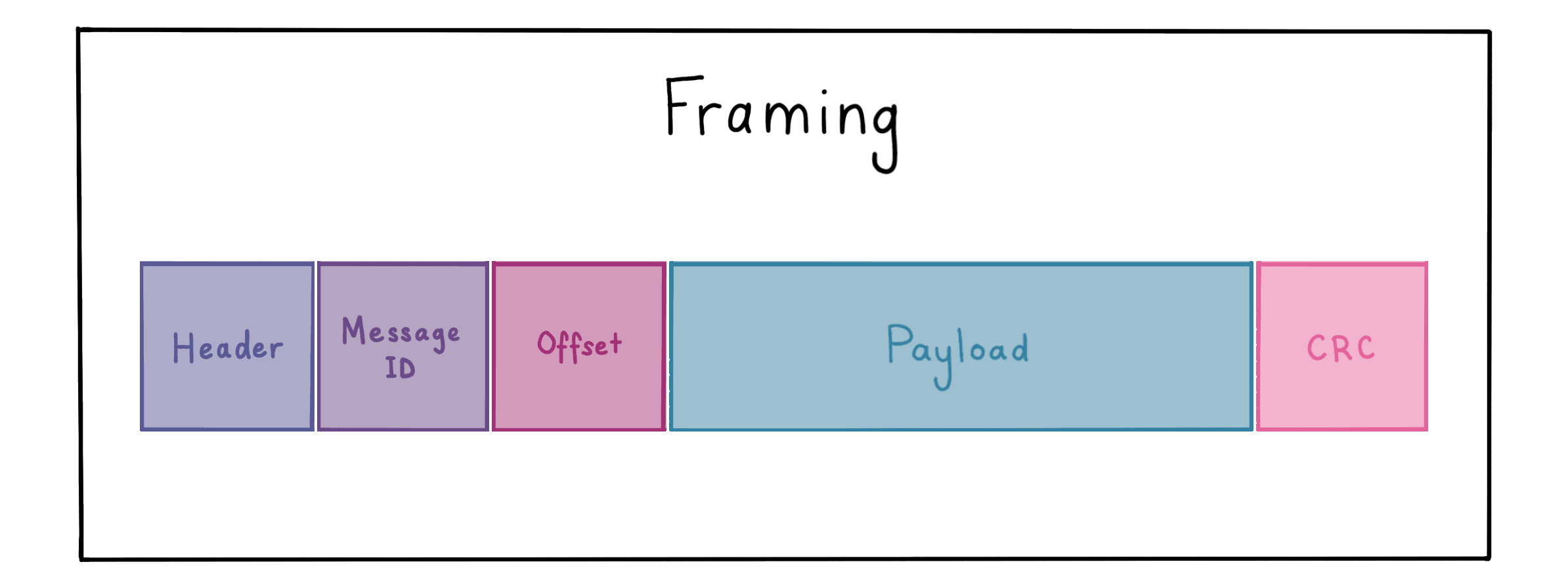
Anatomy of a packet
Packets consist of binary data and have a header, message identifier (ASCII, hash or index based), optional offset metadata for multi-packet payloads, payload data, and a checksum.

The packets are then encoded using the COBS framing algorithm.
Endianness
As the protocol is designed for interoperability with microcontrollers and modern systems, data is in the Little Endian format (LE). We don't use Network Order because these packets aren't subject to historical standards.
If you are using a big endian system, we suggest the recommended reading here $TODO.
Header
The header stores feature flags, sizing and type information, and uses 3-bytes of space. Feature bitflags operate independent of each other.
| Data | Bits Allocated | Description |
|---|---|---|
| Payload Length | 10 | Size in bytes up to 1024 bytes. >0 lengths implies intent to write data. |
| Payload Type | 4 | |
| Message ID Length | 4 | Size in bytes up to 15 |
| Internal Message Flag | 1 | High when packet is for internal use (outside the developer's scope) |
| Offset Payload Flag | 1 | High when packet uses the payload offset word. |
| Response Flag | 1 | When high, a response with the current value of the target variable is returned. |
| Sequence Number | 3 | For non-zero sequence numbers, we expect an acknowledgement with the same sequence number. |
The packing of this data into the header bytes minimises effects of word alignment padding.
| Bytes | 1 | 2 | 3 | |||||||||||||||||||||
|---|---|---|---|---|---|---|---|---|---|---|---|---|---|---|---|---|---|---|---|---|---|---|---|---|
| Bits | 1 | 2 | 3 | 4 | 5 | 6 | 7 | 8 | 1 | 2 | 3 | 4 | 5 | 6 | 7 | 8 | 1 | 2 | 3 | 4 | 5 | 6 | 7 | 8 |
| Data | Payload Length | Type | Internal | Offset | ID Length | Query | Sequence | |||||||||||||||||
Writing data (payload length > 0) and query should trigger a response with the new data, not the previous data.
Types
The payload type field allows for automatic conversions on the UI side. These type values complement stdint.hs standard type schemes ( uint8_t, int32_t etc ).
| Index | Type | Bytes | Description | Range |
|---|---|---|---|---|
| 0 | Callback | 0 | Used to trigger a function call or event | n/a |
| 1 | Custom | n/a | Follows data structure's memory model | Limitless! |
| 2 | Offset Metadata | n/a | ||
| 3 | Byte | 1 | ||
| 4 | Character | 1 | Character (intended to be printable). Character arrays are strings | |
| 5 | int8 | 1 | Signed 8-bit integer | ±127 |
| 6 | uint8 | 1 | Unsigned 8-bit integer | +255 |
| 7 | int16 | 2 | Signed 16-bit integer | ±32,767 |
| 8 | uint16 | 2 | Unsigned 16-bit integer | +65,535 |
| 9 | int32 | 4 | Signed 32-bit integer | ±2,147,483,647 |
| 10 | uint32 | 4 | Unsigned 32-bit integer | +4,294,967,295 |
| 11 | float | 4 | Standard precision floating point value | ±3.4E+38 |
| 12 | double | 8 | Double precision floating point | ±1.7E+308 |
64-bit integers aren't commonly used on embedded systems, so we recommend using a custom type which allows for more intuitive handling on the UI side.
Message Identifier
The message identifier (often abbreviated as msgID) is a variable number of bytes which denote the transmitted variable.
The default implementation suggests a ASCII formatted string with <=15 character length. This scheme allows for human-readable nmemonic identifiers on the embedded and UI side, aiding in usability and debugging, while allowing easy referencing in the application layer.
The protocol does force 1-byte ID minimum lengths, however there is no restriction on the data. Non-printable characters are legal, and simple modifications to the ID system allow index based identifiers to save precious bytes on constrained or production systems.
While the protocol technically supports a far larger[^2] number of unique messageID's than recommended, your design should use no more than a dozen or two (more suggests architectural issues, read the Custom Types documentation).
Offset (optional)
Truthy offset bit values enable a 16-bit address offset from the base address of the variable. This adds support for large data structures and arrays, even with a small packet size.
Payload
Payload data formatting matches the native device representations, little-endian formatted data structure held in memory.
This allows for low-cost output of the data and a simple direct memory copy from the valid inbound packet to the variable.
Checksum
A 2-byte checksum word is at the end of each packet. We use the CRC16-CCITT-FALSE checksum with a seed word of 0xFFFF, processed on the embedded side as data streams in/out.
One notable aspect of cyclic redundancy check algorithms is ensuring that the common failure modes will not trigger with real-world data, and the collision space is sufficiently large to reasonably avoid false-positives. The tradeoff between implementation overhead (bandwidth, memory, code space) favours lower-end microcontrollers.
Of particular interest with our selected CRC implementation, it will self-nullify when presented with bytes matching the current working CRC value.
- We seed with
0xFFFF, - If the first bytes processed are also
0xFFFF, the output CRC will be0x0000, - when followed by at least 2 successive
0x00bytes, the CRC will not be unique while the chain of0x00bytes continues.
This is not an issue for our packet layout, as the header doesn't allow a series of problematic bytes to occur due to the natural ordering of bits.
Encoding scheme
We take the entire packet described above (header through to checksum) and encode it using the lightweight Consistent Overhead Byte Stuffing (COBS) algorithm.
The operating theory is rather simple, for any value 0x00 in our packet, we replace it with an offset value describing the number of bytes we expect to count before the next 0x00 byte.
Because we no longer have any 0x00 bytes in our data, we can use the 0x00 byte as our reserved delimiter character, which provides frame synchronisation.
DIAGRAM HERE
This approach ensures the overhead is one byte per 255 bytes, and allows the parsing statemachines to instantly reset if any of the reserved 0x00 bytes appear. Failing fast means we lose, at most, the one packet if errors cause erraneous behaviour.
DIAGRAM/EXAMPLES OF HOW THIS SAVES US
Considerations
While developing a solid and reliable protocol has been a priority, it does not provide guarantees for information sensitive or safety critical applications. We strongly recommend finding or developing a suitable protocol for applications where message reliability, timing, error identification or cryptographic safety is required.
Protocol Functionality
While the underlying protocol is basic, the UI uses internally namespaced messages to provide connection monitoring, handshakes and fault recovery.
Handshaking and Device Discovery
Heartbeat Monitoring and Link Failover
Automatic retries and error handling
Offset Packets
Electric UI's default protocol supports up to 1kB payload transfers per packet, though the default payload length is smaller to help keep the inbound buffer slim.
1kB packets don't go far with images or buffered streams of sensor data, and we don't want to send arrays between the microcontroller and PC element-by-element either!
Electric UI has an automatic solution to splitting larger data structures into multiple messages. By providing a 16-bit payload offset value we are able to send, recieve and query smaller parts of a larger block of memory.
Diagram of multiple offset messages (long bitstream with arrows pointing to packets and explaining the offset)The UI maintains a copy of the data structure, and will fill sections in as required. Partial updates allow the UI to specifically write to a given position inside the variable's memory.
This bandwidth reduction technique is automatically used when UI actions trigger a write of the large variable.
[^1]: Developer configurable settings can tweak underlying overheads. [^2]: 25515 uniques, or about an undecillion, about 200 million of which are printable