This guide describes how to get running with the electricui-embedded C library in a baremetal project, using Silicon Labs's vendor HAL and SimplicityStudio V5.
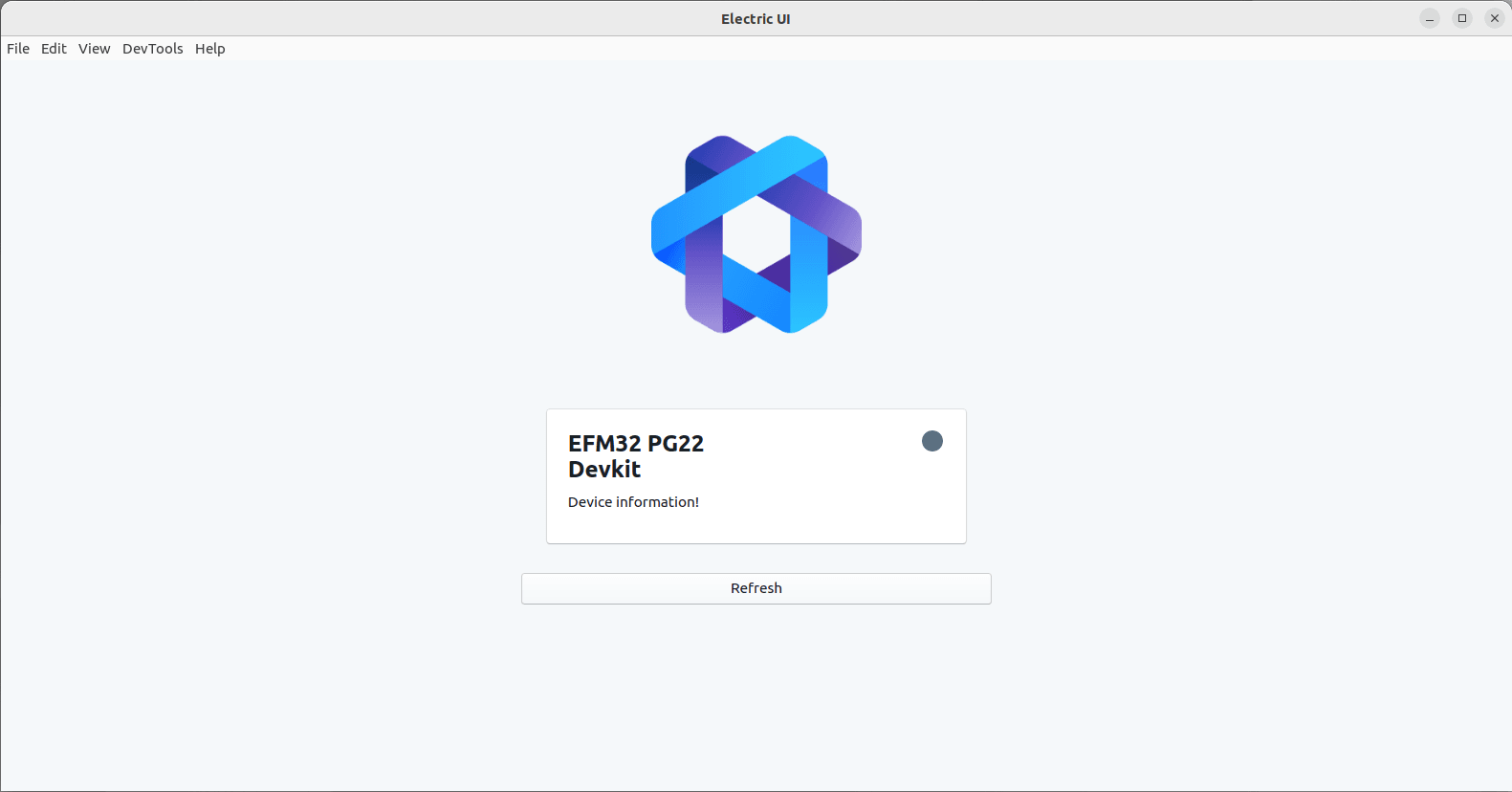
The resulting firmware will match the behaviour of the hello-eui firmware in the getting started tutorials, allowing for a user-adjustable blink time alongside a plot of LED state.
This guide assumes an EFM32 development board, we're using the feature rich and affordable PG22-DK2503A. You'll also need a way to connect to the hardware UART with a suitable USB-Serial adaptor, or using your devkit's onboard programmer VCOM passthrough.
The USART integration featured is deliberately simple - production firmware should consider DMA backed UART for better performance and power management.
Create a Silicon Labs account to access the download,
Unpack and install the IDE, and launch it,
On Linux, the 'install' is just extracting the entire folder into your home directory and running setup.sh.
Launch it with ./studio or ./studiowayland.sh if you're lucky enough to be running a modern desktop environment.
Sign-in to access the integrated downloads, and it'll run off and update. Reload as necessary.
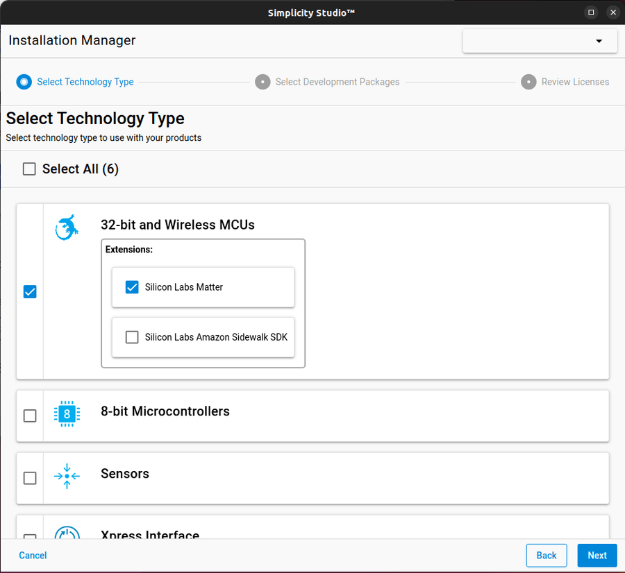
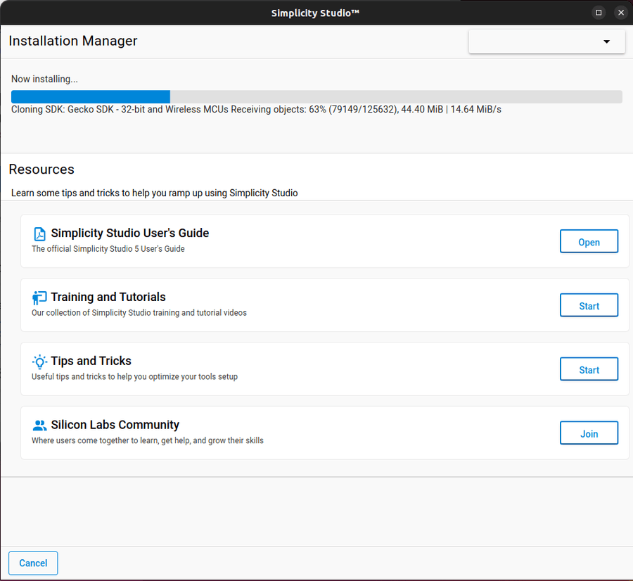
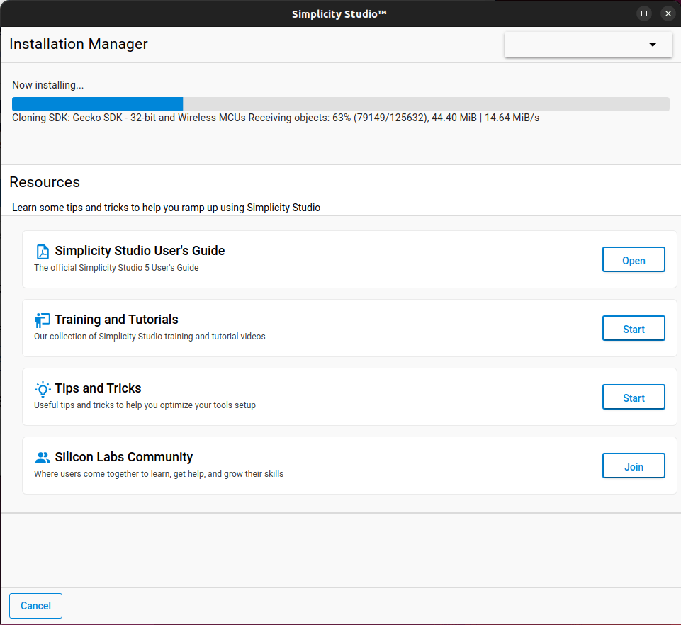
Install the 32-bit SDK support package, and any others as needed for your platform and project.
This involves a many-GB git pull, so go grab a snack!
On my Ubuntu 22.04 test machine, I needed to manually resolve hardware permissions issues - even though setup documentation explicitly mentions setup.sh handling this automatically for Ubuntu flavoured Linux systems.
JLink permissions issue
Initially I hit an error along the lines of Silicon Labs USB Debug Adapter returns "(ID:null)" on "Debug Adapters". The onboard JLink programmer is detected, but can't be properly communicated or used by SimplicityStudio. The issue is caused restrictive default permissions.
On Ubuntu, I used lsusb to identify the debugger's USB VID and PID values:
scott@devel-vm:~$ lsusb
Bus 003 Device 001: ID 1d6b:0003 Linux Foundation 3.0 root hub
Bus 002 Device 004: ID 1366:0105 SEGGER J-Link OB
Then create a udev rules file sudo nano /etc/udev/rules.d/70-silabs.rules and added an entry using the VID and PID values from above.
Then reload the rule with sudo udevadm control --reload-rules, and unplug/replug the board. In my instance, I also needed to restart Simplicity Studio for it to correctly connect after this change.
Virtual COM passthrough permissions
Serial permissions issues are normal for fresh Ubuntu installs - my user didn't have permission to access the serial-port being provided alongside the debug probe.
We can list the serial ports with ls -la /dev/tty* and see that our probe presents /dev/ttyACM0 when connected
It's owned by the dialout group.
Running groups $USER shows us that our account isn't a member of dialout.
Adding ourselves to dialout by running sudo usermod -a -G dialout $USER
You'll need to log out for this to take effect.
Project creation & Setup
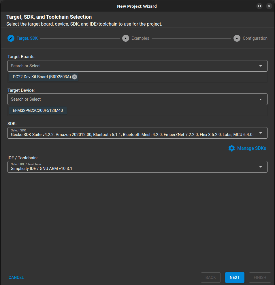
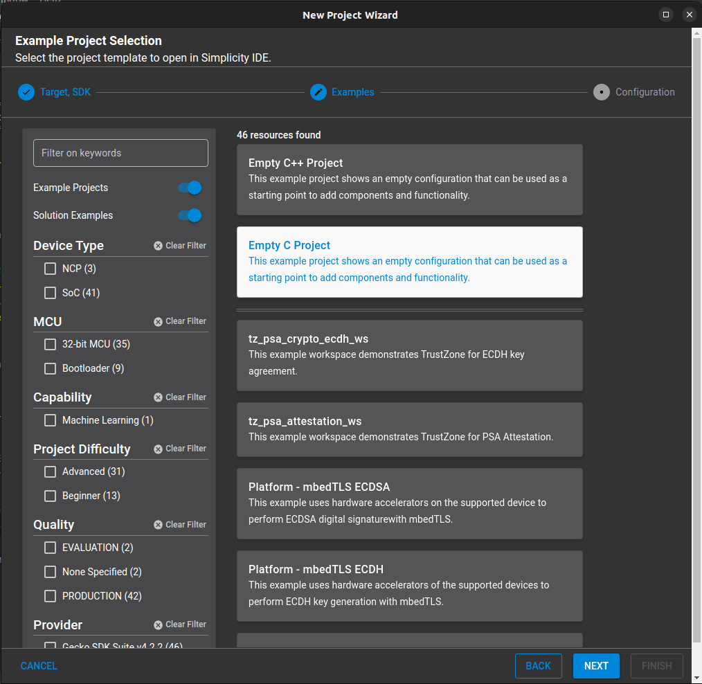
We'll use the new project wizard to start. Select the target devkit or microcontroller, along with the SDK and toolchain.
You can opt to start from one of the existing example projects, but we'll create an empty C project and get it running from scratch.
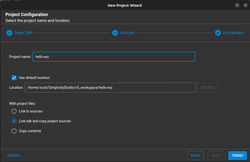
Hit next and enter a good name for the project directory. I prefer to copy the vendor sources into the project structure instead of linking.
Hardware Configuration
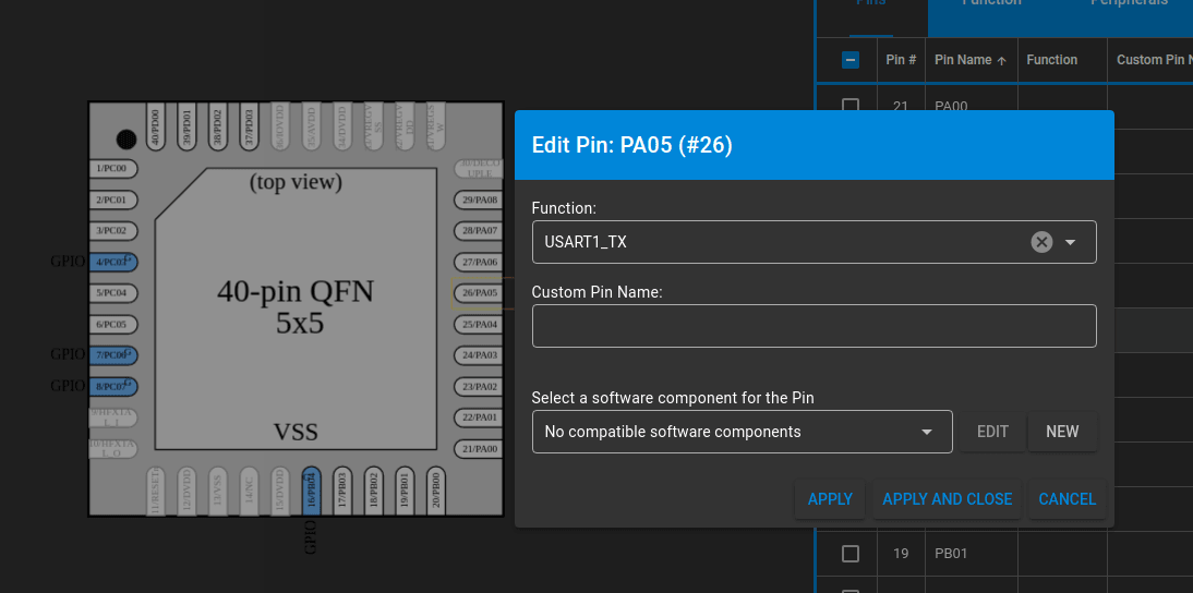
First we need to prepare the hardware peripherals for UART communication and LED control. For the PG22 dev-kit I'm using, the vcom TX/RX are on PA05 and PA06, and the user LED is on PA04. This information can be found in the matching dev-kit user-guide, or data-sheet for your choice of microcontroller.
Open up graphical pin definition editor by opening the .pintool file in the root of the project.
First we'll start by assigning USART1 _TX to PA05 and then adding a new software module.
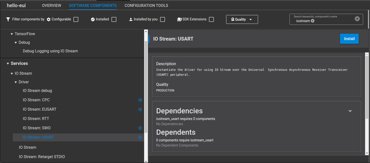
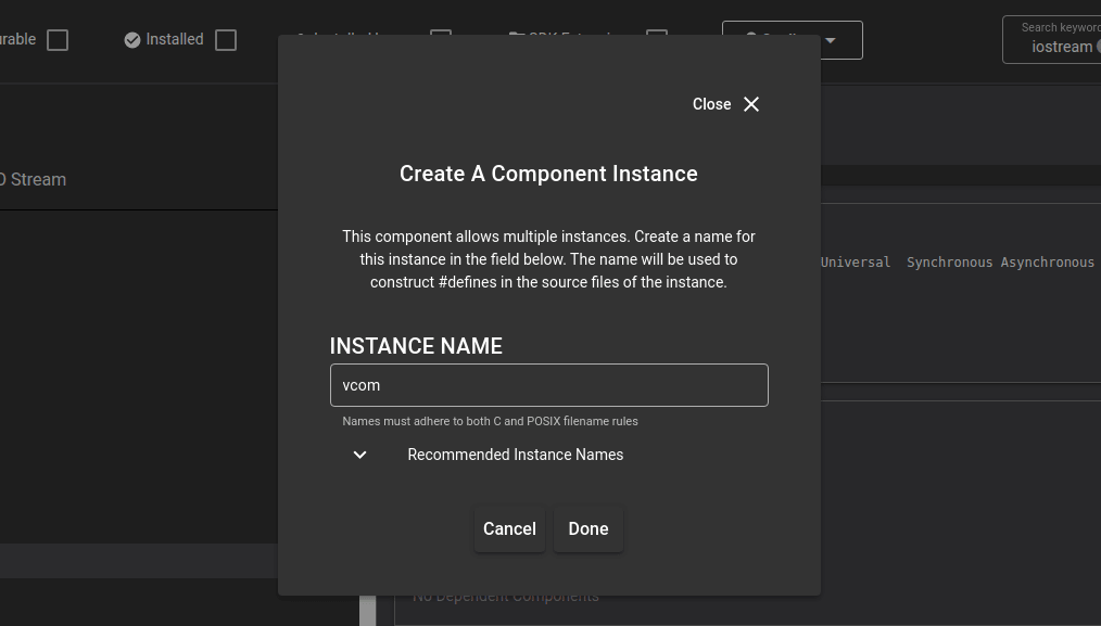
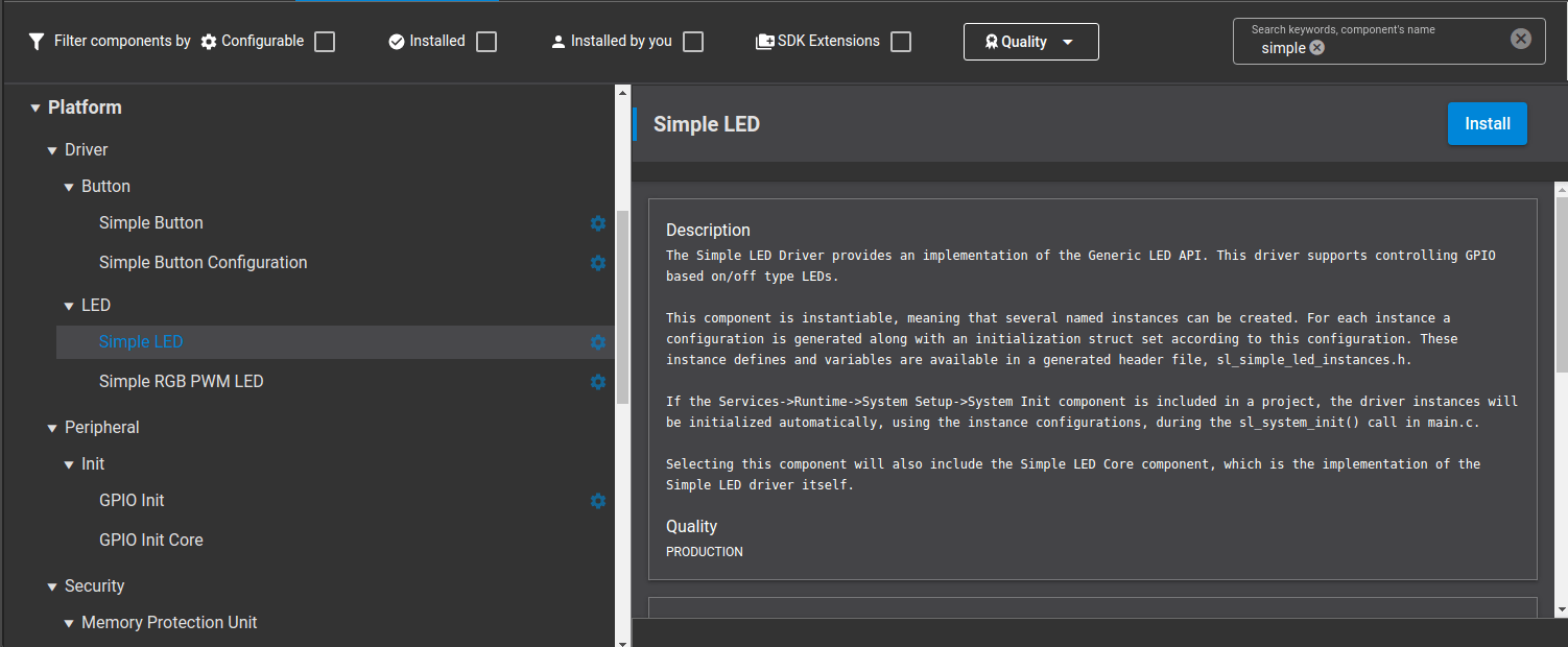
Find the IO Stream: USART software module and click install, giving it an instance name vcom.
Back in the pintool we can see the other USART pins have been assigned. We repeat the process for the onboard LED on PA04 using the SimpleLED module, naming it led0.
We also add the software module SleepTimer which will provide the underlying timing for our adjustable LED blink behaviour.
Programmer Setup
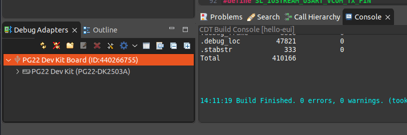
Check the JLink programmer is configured in the bottom left window pane in Simplicity Studio "Debug Adaptors".
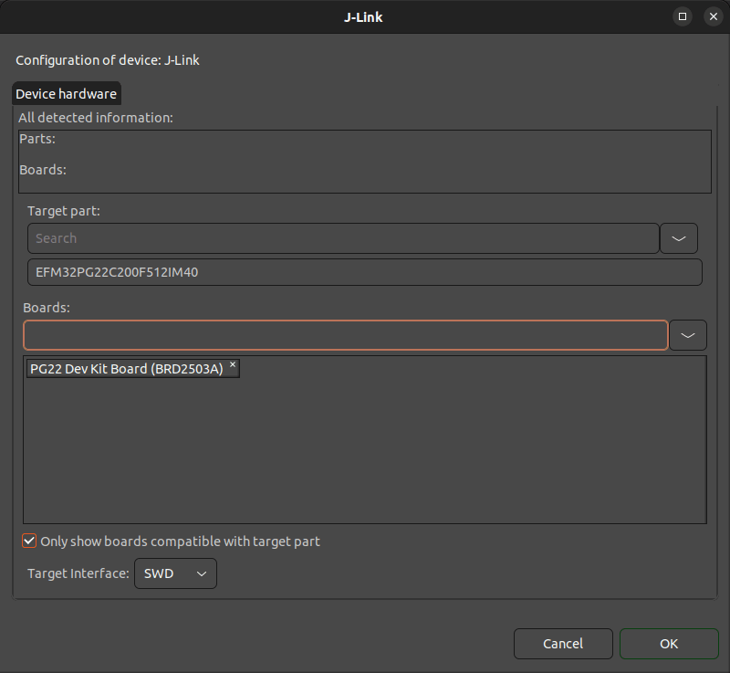
If it didn't auto-detect, click the little spanner icon and choose either the microcontroller or devkit you're using. Make sure the target interface is set to SWD.
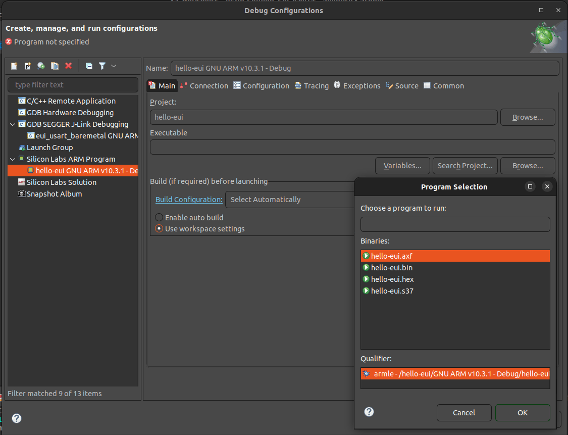
While we're here, create a debug configuration by clicking on the 'bug' icon on the left side of the top toolbar.
Create a new "Silicon Labs ARM Program" entry, and select the build .axf file which we will want to flash to hardware. I found the auto-detect of the programmer and settings to work fine, but if needed, set these in the connection tab.
Implement LED blink
Create a .h/.c pair called app_eui_usart or similar, and stub out some simple functions for setup and processing that we'll put in the project's auto-generated super-loop functions.
#ifndefAPP_EUI_USART_H
#defineAPP_EUI_USART_H
voidapp_eui_usart_init(void);
voidapp_eui_usart_process(void);
#endif// APP_EUI_USART_H
In the .c, we'll import the header, some headers for our hardware modules, and setup a basic LED blinker.
This is essentially unchanged from the baremetal-blink example project - sleeptimer is configured to fire a callback after a glow_time duration passes, and the LED state is set in the on_timeout callback.
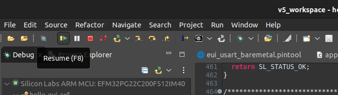
The default behaviour after flashing is to halt on entry to the main() function, remember to click the resume button (F8) in the top bar of the debug layout.
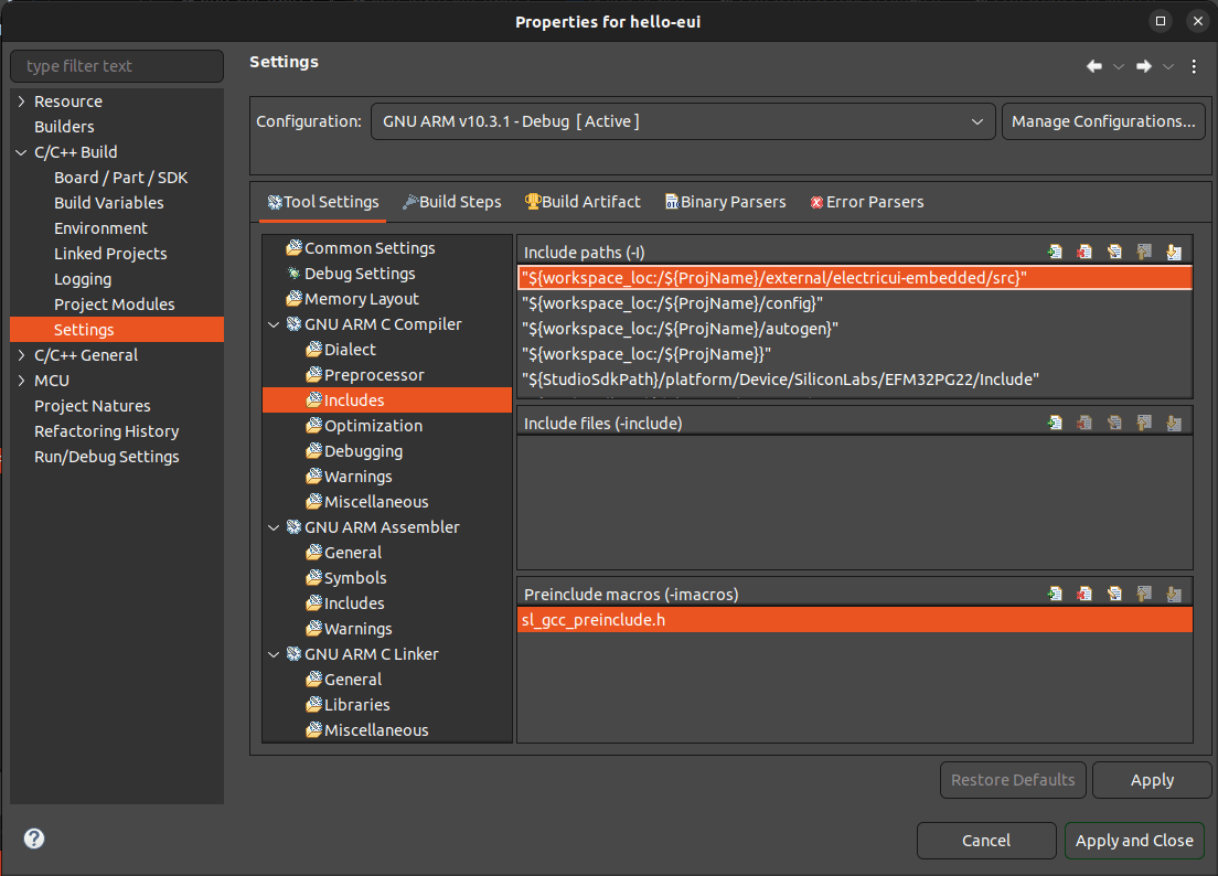
In the project settings (right click on hello-eui in the project explorer view), we'll need to configure the include paths with our new library.
The include paths are hidden in the compiler settings sub-menu which is displayed under "C/C++ Build", "Settings". Inside the "Tool Settings" tab, we'll need to add an entry in the "GNU ARM C Compiler" "Includes" page.
We add the external/electricui-embedded/src folder here with the same workspace/project pathing as the existing config folder generated by Simplicity Studio.
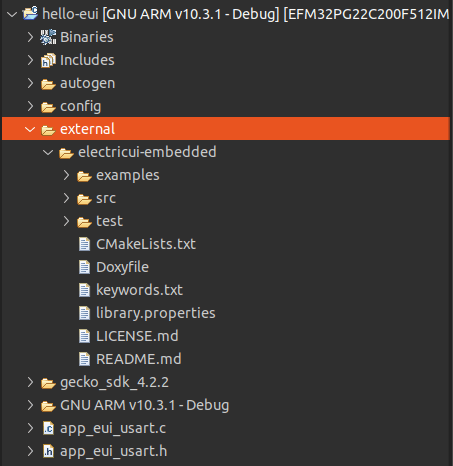
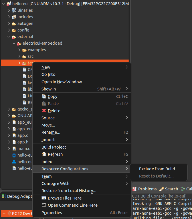
When trying to build, you may find that Eclipse tries to build and link the electricui-embedded unit tests and example projects. Right click on the test and examples folders, navigate to "Resource Configurations" and then "Exclude from Build".
We can now import electricui.h in our app_eui_usart.c file, and connect the variables for our blinking light.
Interface Setup
We'll start by declaring two functions for reading and writing data, and then declare some eui variables.
// Electric UI helps manage variables referenced in this array
eui_message_t tracked_variables[]=
{
// We'll add variables here later on...
};
For run-time initialisation, we use some setup functions which tell the library which interface to use and what variables to track.
We also give eUI a board identifier which allows the UI to distinguish between otherwise identical connected hardware/firmware. We recommend using the chip ID where possible, and for EFM32 parts this can be read out of the DEVINFO memory locations.
The EUI_TRACK macro simplifies handling the tracked array element count, the manual approach looks like this:
eui_setup_tracked( &tracked_variables, 3 );
Likewise, if you're using an array of eui_interface_t, then use the EUI_LINK helper macro.
We'll finish off by stubbing out the serial interaction functions we declared and told eui about earlier. Using the IOStream library makes this rather straightforward:
If you opted to base your project on one of the USART examples, ensure that the iostream config file has the SL_IOSTREAM_USART_VCOM_CONVERT_BY_DEFAULT_LF_TO_CRLF define is to the default of 0 .
The stdio iostream example sets this to 1 for a cleaner looking loopback demo, but will cause issues with the binary formatted packets sent by Electric UI.
Tracking variables
Tracked variables make sharing variables between the UI and microcontroller easier. The library will announce these variables to the UI during a handshake, and handles incoming queries or writes as needed.
Variables are defined and used as normal, and we 'track' them by adding entries into the eui_message_t array before startup. Each eui_message_t contains a pointer to it's variable along with some simple type information.
Lets add a human-readable nickname string for the board alongside our led_state and glow_time variables, and then add them to the tracked variable list using helper macros.
By using macros with standard types, the embedded library and UI are able to use default codecs to handle data representation.
// Electric UI manages variables referenced in this array
eui_message_t tracked_variables[]=
{
EUI_UINT8("led_state", led_state ),
EUI_UINT16("lit_time", glow_time ),
EUI_CHAR_ARRAY_RO("name", nickname ),
};
In our timeout callback, we should also reset the timer periodically with updated glow_time values as user interface interactions change it. If we didn't, the sleeptimer library would continue firing callbacks at the interval set during init.
If you have any questions, comments or need help getting Electric UI to integrate with your Silicon Labs project, get in touch!
With the basic integration in place, read our other guides to expanding functionality and understand how to build a great user interface for your SiLabs microcontroller.