ESP32
This guide describes how to get running with the electricui-embedded C library while using esp-idf. If you are trying to use the Arduino toolchain, install the ESP8266 or ESP32 Arduino core, and follow the standard Arduino Instructions.
This guide assumes you have an ESP32 development board, and a suitable USB-Serial adaptor if your devkit doesn't have one onboard. For more resources on working with ESP boards, we Espressif's Developer Zone is the first point of reference.
Toolchain Preflight Check
If you haven't successfully flashed a basic helloworld program to your board, you should setup your development environment. The official ESPRESSIF Getting Started Guide is the best place to start.
This guide assumes that bidirectional serial communications are working before Electric UI is integrated.
A quick summary if you haven't done this before:
-
Follow the instructions to create a new idf project, and open up a text editor to modify
main.c, -
Reference the
uart_echoexample on GitHub to configure UART echo on IO4 (TX) and IO5 (RX). Change the pin selections to match devkit hardware as required. -
Flash to your hardware with
idf.py flash. -
Connect a USB-Serial adapter's RX pin to the ESP32 IO4, TX to IO5, and adapter ground to GND,
-
Open a serial terminal connected to the USB serial adapter.
-
Enter text into the monitor and watch the device send data back!
Using the onboard USB-Serial programming port for these tests and Electric UI is possible, but we recommend keeping UART0 reserved for programming and logging during development.
If you want to use UART0 with Electric UI, disable the logging output:
- Run
idf.py menuconfig,- Select "Component Config", "Log output", "Default Log verbosity (info)"
- Select "Error" or "No Output" to supress the default text logs.
- Press
Qto quit and save your changes.
Integrating the Electric UI C library
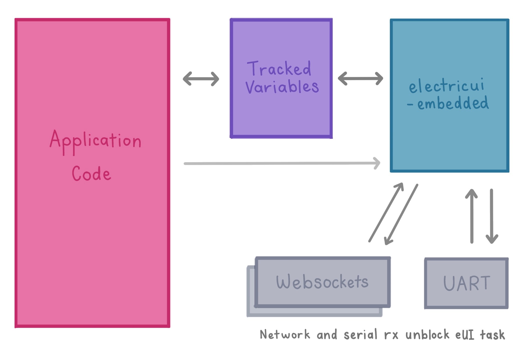
While a little more complicated than dropping a bare-minimum example into app_main(), the architecture outlined below demonstrates one possible integration approach[^1]. Decoupling the supervisor/main tasks from Electric UI lets the developer maintain stricter scoping rules and reduce inappropriate subsystem interdependencies.
UART (and other communication methods like websockets) are typically event driven and can be integrated alongside the electricui-embedded, or can use inter-task communications methods such as stream-buffers.
We're going to add a new CMake Component to our project called eui_handler which will be responsible for managing the Electric UI library setup, communication over UART, and later expanded to communicate with a websockets task.
In this example, we'll treat our main.c as our supervisor task, responsible for our program's primary LED blinker task. Then we'll connect those variables to Electric UI and add serial communications.
[^1]: Depending on application complexity and number of variables shared to the UI, the tracked variables can be owned by the eui handler task and accessed with a getter/setter pattern. Alternatively, system level events can be generated to notify other tasks of commands or data.
LED Blink Task
Open main.c and create a new task to setup a GPIO output for a blinker LED, then toggle the LED periodically. This blinker implementation matches the hello-electric blink demo.
Change the GPIO define as needed to match your devboard.
#include <stdio.h>#include "freertos/FreeRTOS.h"#include "freertos/task.h"#include "driver/gpio.h"#define GPIO_LED 13uint8_t blink_enable = 1; // if the blinker should be runninguint8_t led_state = 0; // track if the LED is illuminateduint16_t glow_time = 200; // in millisecondsuint32_t led_timer = 0;void blink_task(void *pvParameter){ // Configure the onboard LED to output push-pull mode gpio_pad_select_gpio(GPIO_LED); gpio_set_direction(GPIO_LED, GPIO_MODE_OUTPUT); led_timer = xTaskGetTickCount(); while(1) { if( blink_enable ) { // Check if the LED has been on for the configured duration uint32_t tick_time = xTaskGetTickCount() * portTICK_PERIOD_MS; if( tick_time - led_timer >= glow_time ) { led_state = !led_state; //invert led state led_timer = tick_time; } } gpio_set_level(GPIO_LED, led_state); vTaskDelay(pdMS_TO_TICKS( 10 )); }}void app_main(void){ xTaskCreate( &blink_task, "blink_task", configMINIMAL_STACK_SIZE, NULL, 8, NULL);}This simple task checks to see if it should toggle the LED, based on the blink_enable flag and the time since the last toggle occurred.
The task then blocks, and FreeRTOS will come back to the blink_task after ~10ms have elapsed to re-evaluate the LED state.
Now we'll add control over the LED behaviour with a UI!
Creating an eui_handler component
-
Create the
/projectname/components/eui_handlercomponent folder, -
Inside it, create a pair of files,
eui_handler.handeui_handler.c, -
Download the latest stable release of
electricui-embeddedfrom GitHub into/components/eui/electricui-embedded. We recommend using git:git clone https://github.com/electricui/electricui-embedded.git -
Create a file
/components/electricui/CMakeLists.txtwhich points to the library paths:idf_component_register(SRCS "eui_handler.c" "electricui-embedded/src/electricui.c" "electricui-embedded/src/eui_utilities.c" "electricui-embedded/src/transports/eui_binary_transport.c" INCLUDE_DIRS "." "electricui-embedded/src" "electricui-embedded/src/transports" )
Once this is done, the project folder structure will look similar to this:
├── components│ └── eui_handler│ ├── electricui-embedded│ │ ├── examples│ │ ├── src│ │ ├── test│ │ ├── Doxyfile│ │ ├── keywords.txt│ │ ├── library.properties│ │ ├── LICENCE.md│ │ └── README.md│ ├── CMakeLists.txt│ ├── eui_handler.c│ └── eui_handler.h├── main│ ├── CMakeLists.txt│ ├── component.mk│ └── main.c├── CMakeLists.txt├── Makefile└── sdkconfigElectric UI and UART configuration will be performed by a task in eui_handler.c started from app_main(). After setup, the task will wait for serial data to feed to Electric UI.
Serial handling
To start with, edit eui_handler.h to add the handler's task function prototype (the public facing API surface of the helper).
Also, setup a structure so our app_main() can pass some information to the handler during task creation. The structure needs to contain the pointer to the tracked variables, and the number of array items.
#include "electricui.h"typedef struct{ eui_message_t *variables_p; size_t count;} handler_shared_vars_t;void eui_handler_task(void *pvParameter);Now edit eui_handler.c to build out the eui_handler_task().
-
Create a callback function
serial_write()and give it to aeui_interface_t. When Electric UI needs to respond to an inbound packet, this callback is responsible for sending the buffer over UART. -
Setup the IDF's UART driver's built-in event queue functionality on pins IO17 and IO18.
Change the
UART_RXandUART_TXpin defines if you've connected to different pins.
- Create an inbound buffer and
uart_event_tto hold the inbound event's data. - Setup Electric UI, using the tracked variables passed via
*pvParameterwith thehandler_shared_vars_t. - The loop will block until an inbound UART event is generated. When it unblocks, pass the data to
eui_parse().
#include <string.h>#include "freertos/FreeRTOS.h"#include "freertos/task.h"#include "driver/uart.h"#include "driver/gpio.h"#include "eui_handler.h"#define EXTERNAL_UART UART_NUM_2#define UART_TX 17#define UART_RX 16#define BUF_SIZE (128)// Callback function for outbound eUI packetsstatic void serial_write( uint8_t *data, uint16_t len );static eui_interface_t serial_comms = EUI_INTERFACE( &serial_write );void eui_handler_task(void *pvParameter){ // Setup the UART uart_config_t uart_config = { .baud_rate = 115200, .data_bits = UART_DATA_8_BITS, .parity = UART_PARITY_DISABLE, .stop_bits = UART_STOP_BITS_1, .flow_ctrl = UART_HW_FLOWCTRL_DISABLE, .source_clk = UART_SCLK_APB, }; QueueHandle_t uart2_queue; uart_driver_install(EXTERNAL_UART, BUF_SIZE * 2, BUF_SIZE * 2, 20, &uart2_queue, 0); uart_param_config(EXTERNAL_UART, &uart_config); uart_set_pin(EXTERNAL_UART, UART_TX, UART_RX, UART_PIN_NO_CHANGE, UART_PIN_NO_CHANGE); // Create a buffer for an inbound uart data event uart_event_t event; uint16_t rx_read = 0; uint8_t* dtmp = (uint8_t*) malloc(BUF_SIZE); // Setup Electric UI with tracked variable array passed in during task creation if( pvParameter ) { handler_shared_vars_t main_tracked = *((handler_shared_vars_t *)pvParameter); eui_setup_tracked( main_tracked.variables_p, main_tracked.count ); } eui_setup_interface( &serial_comms ); eui_setup_identifier( "hello", 5 ); while(1) { // Wait for a UART event if( xQueueReceive(uart2_queue, (void * )&event, (portTickType)portMAX_DELAY) ) { bzero(dtmp, BUF_SIZE); switch(event.type) { case UART_DATA: rx_read = uart_read_bytes(EXTERNAL_UART, dtmp, event.size, portMAX_DELAY); if( rx_read > 0 ) { for( uint16_t i = 0; i < rx_read; i++) { eui_parse( dtmp[i], &serial_comms ); // Ingest a byte } } break; case UART_FIFO_OVF: uart_flush_input(EXTERNAL_UART); xQueueReset(uart2_queue); break; case UART_BUFFER_FULL: uart_flush_input(EXTERNAL_UART); xQueueReset(uart2_queue); break; default: break; } } } free(dtmp); dtmp = NULL; vTaskDelete(NULL);}static void serial_write( uint8_t *data, uint16_t len ){ uart_write_bytes(EXTERNAL_UART, (const char *)data, len);}There isn't really that much happening here. We just need to make sure the eui_handler_task() is created in our main, and finish tracking our blinker variables.
Tracking blink variables
Tracked variables make sharing data between the UI and ESP32 easier. The library will announce these variables to the UI during a handshake, and handles incoming queries or responses automatically.
Variables are defined and used as normal, and we 'track' them by adding entries into a eui_message_t array. Each eui_message_t contains a pointer to the variable, and some identifying information. We use some macros to make this more ergonomic.
#include "eui_handler.h"char nickname[] = "ESP32 UART";// Electric UI manages variables referenced in this arrayeui_message_t tracked_variables[] ={ EUI_CHAR_ARRAY_RO( "name", nickname ), EUI_UINT8( "led_blink", blink_enable ), EUI_UINT8( "led_state", led_state ), EUI_UINT16( "lit_time", glow_time ),};Tracked variables are covered in more detail in the baremetal C guide.
To finish connecting things up, we need to create a handler_shared_vars_t structure with a pointer to our tracked variables. We'll send this structure data to the handler when we create the task.
#include "eui_handler.h"handler_shared_vars_t share_tracked = { .variables_p = &tracked_variables, .count = EUI_ARR_ELEM(tracked_variables) };void app_main(void){ xTaskCreate( &eui_handler_task, "eui_task", 2048, (void *)&share_tracked, 5, NULL); xTaskCreate( &blink_task, "blink_task", configMINIMAL_STACK_SIZE, NULL, 8, NULL);}To recap: the variables controlling the LED blink behaviour are managed by Electric UI, and our eui_handler_task is setup and ready for serial communication.
Build and flash the project to hardware with idf.py flash, and test it out!