Embedded Basics
If you're experienced with embedded development, skip to the setup summary here.
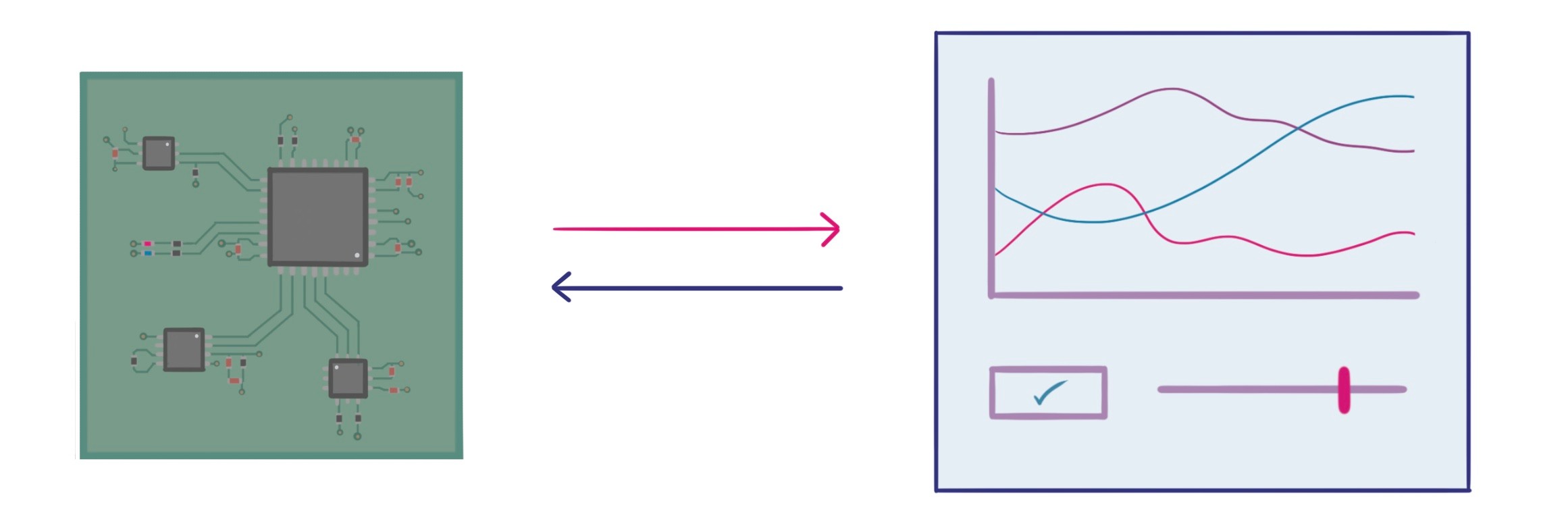
How does my hardware talk to the UI?
When desktop or mobile software needs to connect to hardware, there needs to be a common language which the hardware and computer use to share information. This is commonly done over a direct Serial, USB, WiFi or Bluetooth connection.
Quite often simple hardware projects send human readable text (ASCII) to a Python or MATLAB script as a set of formatted strings (i.e comma-delimited etc). This style of communications has a few key drawbacks:
- Sending data in ASCII format is inefficient - a floating point value like
362.357221needs 10 ASCII bytes to be transferred, while a binary representation uses 4-bytes, - Corruptions and errors can cause funny results, or allow incorrect data to be displayed,
- It's often tedious to iterate beyond a simple prototype as formatting and parsing code changes as new variables are added or their type changes.
By specifying how data is formatted and expected behaviours for sending and receiving data, the hardware and software can agree on how data is exchanged between the devices. This is called the communications protocol. Some protocols focus on communicating between only two devices, to many devices through a mesh, or over the internet!
More mature protocols also provide extra features such as: invoking a function instead of sending data, error checking, compression or encryption, handling structured data, or just providing better abstractions over the interaction between machines sharing data.
electricui-embedded provides an implementation of a binary communications protocol intended to make direct communication between microcontrollers and computers simple, whilst being technically efficient and reliable.
Electric UI Embedded
The library is written in C, has no external dependencies, and aims for a reasonably light footprint. It requires a callback function to write a buffers to your communications transport and accepts data as it arrives at the microcontroller.
- Ensure your micro-controller has functioning bidirectional data transfer with your computer (wired serial connections are easiest to start with).
- Download the
electricui-embeddedlibrary from Github. - Import it into your project,
- Follow the bundled example implementations to declare tracked variables, provide inbound data, and setup a callback function for sending packets back to the computer.
The Hardware section of the docs provides long-form setup guides, API reference, and best-practice technical discussions.
As a quick explanation, tracked variables make sending and receiving data from the UI really simple. We declare variables as normal, and pass Electric UI an array of pointers to those variables along with a human readable message identifier.
#include "electricui.h"// User configurable settingsuint8_t blink_enable = 1;uint8_t led_state = 0;uint16_t glow_time = 200;eui_interface_t eui_serial = EUI_INTERFACE( &write_on_serial );eui_message_t tracked_vars[] ={ EUI_UINT8( "led_blink", blink_enable ), EUI_UINT8( "led_state", led_state ), EUI_UINT16( "lit_time", glow_time ),};int main(){ EUI_LINK( eui_serial ); // set the default interface EUI_TRACK( tracked_vars ); // track our variables while(1) { // Check for inbound serial data and give it to Electric UI. while( serial_data_ready() ) { eui_parse( serial_read_byte(), &eui_serial ); } // Toggle a LED every X milliseconds. if( blink_enable ) { // Has the LED has been on for the configured duration if( get_millis() - led_timer >= glow_time ) { led_state = !led_state; // invert led state led_timer = get_millis(); // timer reset } } set_led( led_state ); // update the LED // ... }}void write_on_serial( uint8_t data, uint16_t len){ serial_write(data, len);}We'll be using it for these tutorials and it's probably a good fit for your prototype. Electric UI is designed to work with a range of industry standard protocols as well!
Running the UI sandbox
The arc quickstart guide covered creating a project and launching the development environment.
-
From your project folder, run
arc startfrom your command line, -
Connect your microcontroller to your computer, the UI should detect the board and display it in the connections list.
-
Click on the device card to connect to it.
By default, the first device view will open with a pre-populated graph and components to control the blinking LED.
Time to change the template UI and firmware!
Troubleshooting
Changing the baud rate
The template configuration expects serial based connections at 115200 baud by default.
If your microcontroller configuration uses a different baud rate, edit the serial transport configuration near the top of the /src/transport-manager/config/serial.tsx file.
const serialProducer = new SerialPortHintProducer ({ SerialPort , baudRate : 115200,})If you are using a native USB serial interface, it usually doesn't matter what your configured baud rate is on either end as CDC abstracts it away...
Filtering serial devices
For reduced friction, the template defaults don't filter the list of possible serial devices. To minimise handshake attempts with other devices, restrict search attempts by customising the filtering strings to match your specific hardware.
See the device filters documentation for more details.
Additional troubleshooting
If you are using an Arduino, check the Arduino specific troubleshooting notes.
If you still aren't seeing your hardware, maybe check our more detailed communications troubleshooting page and then send us an email!